LED Light Bulb with Battery Backup and Remote Operation

a technology of battery backup and battery life, which is applied in the direction of semiconductor devices for light sources, with built-in power, lighting and heating apparatus, etc., can solve the problems of not disclosing the upper portion of the modular light bulb, the air vents of the battery shell, and the removable battery housing, so as to prevent the device from failing during power outages and low battery life

Inactive Publication Date: 2012-05-24
ZITTEL MICHAEL
View PDF6 Cites 87 Cited by
  • Summary
  • Abstract
  • Description
  • Claims
  • Application Information

AI Technical Summary

Benefits of technology

[0026]Another object of the present invention is to provide a new and improved LED lighting device having a means for exchanging the battery source to prevent failure of the device during power outages due to low battery life.

Problems solved by technology

These devices have familiar design and structural elements for the purposes of providing general illumination and / or backup lighting, however they are not disclose a modular light bulb shell having air vents for cooling, a cylindrical lighting assembly having LEDs positioned about its surface, or a removable battery housing for providing a backup battery source.
However, they do not disclose a modular bulb having a removable upper portion, a lower shell with air vents for thermal cooling, means for operatively connecting to an incandescent bulb socket, or a cylindrical lighting assembly having LEDs positioned along its outer surface.
The devices disclosed by the prior art do not address the need for remote operation of backup lighting by users who may not be able to easily reach the light bulb during power outages.

Method used


Image

  • LED Light Bulb with Battery Backup and Remote Operation
  • LED Light Bulb with Battery Backup and Remote Operation
  • LED Light Bulb with Battery Backup and Remote Operation

Examples


Embodiment Construction

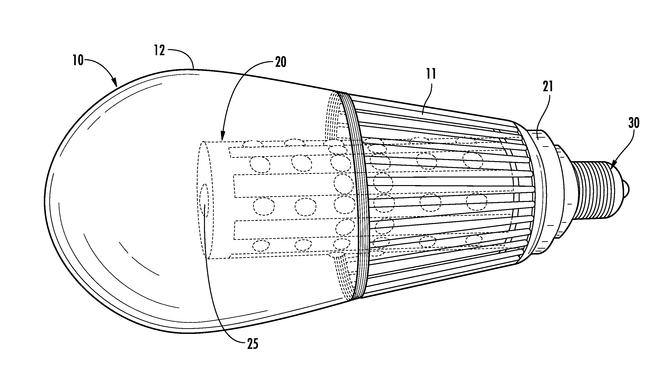
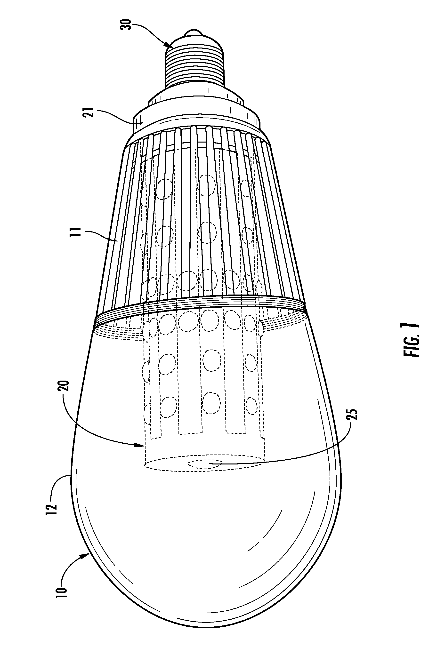
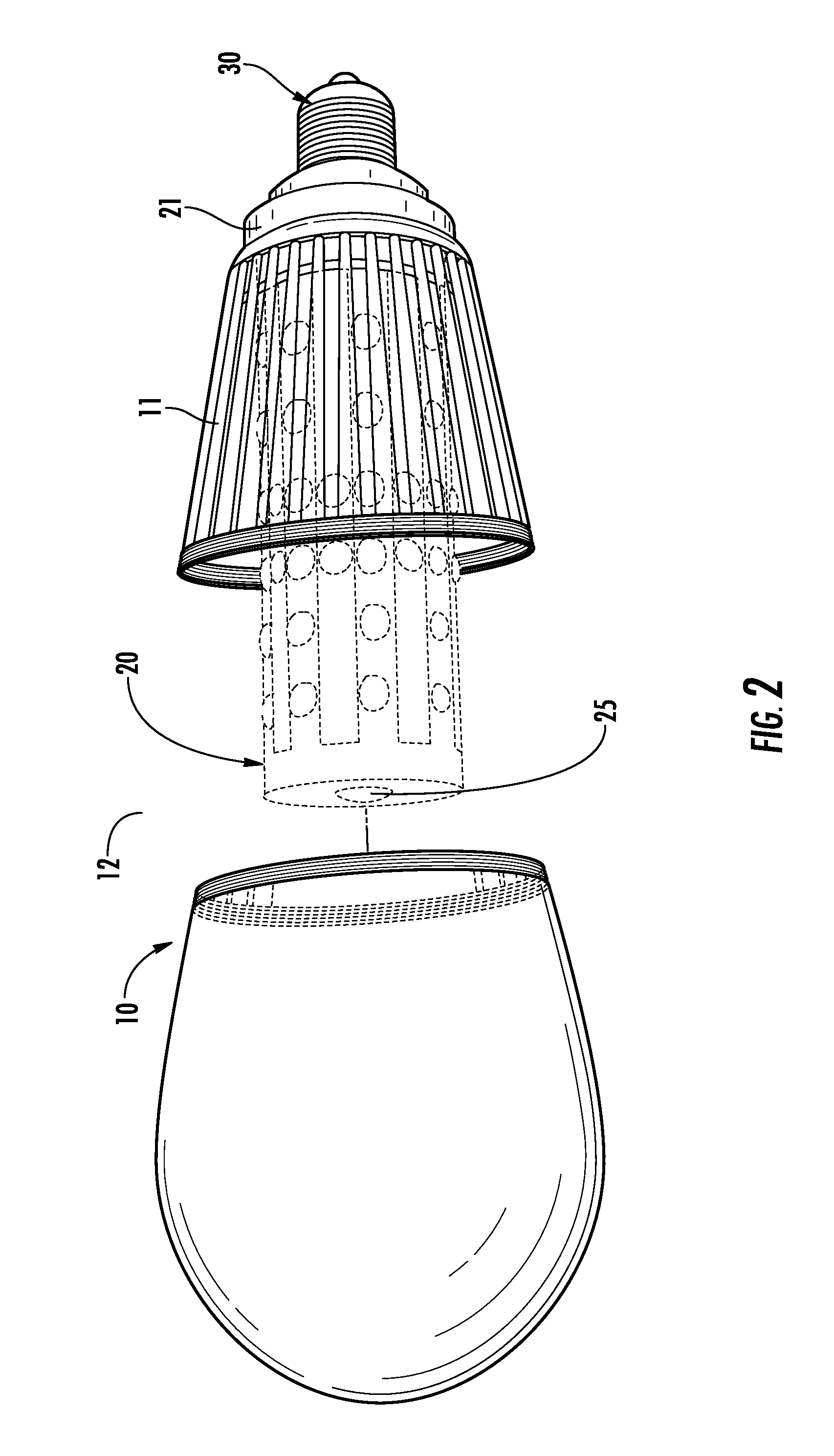
[0033]Reference is made herein to the attached drawings. Like reference numerals are used throughout the drawings to depict like or similar elements of the claimed LED lighting device. For the purposes of presenting a brief and clear description of the present invention, the preferred embodiment will be discussed as used for remote activation of battery powered LED lighting. This is for representative purposes only and should not be considered to be limiting in any respect.

[0034]Referring now to FIGS. 1 & 2, there is shown an LED light bulb according to the present invention. The light bulb has an outer bulb shell 10, an inner lighting assembly 20, and a metal threaded base portion 30. Said outer bulb shell 10 encloses the inner lighting assembly 20 and acts as a housing for the same. The outer bulb shell has a bottom portion 11 and a top portion 12 that are removably secured together by a threaded screw means disposed at the rim of each portion. Air vents are positioned along the s...


PUM


Abstract

An LED lighting device is presented for both general illumination and emergency backup lighting. The device has an outer bulb shell with air vents to release heat. A metal threaded base is adapted to fit into a standard incandescent bulb socket and to allow electrical current to flow into the device. Housed within the outer bulb shell, and removably connecting the shell to the metal base is a lighting assembly. The lighting assembly is a cylindrical structure comprising bright LEDs arranged along its outer surface, some of which are powered via wall outlet power from the metal base of the device, while others utilize an internal battery power source housed within the assembly. The battery powered LEDs may be remotely activated by a remote control means. Use of the remote control sends a signal to a signal receiving means on or within the device that directs the backup LEDs to illuminate.

Description

CROSS REFERENCE TO RELATED APPLICATION[0001]This application claims the benefit of U.S. Provisional Application No. 61 / 484,916 filed on Nov. 18, 2010, entitled “Give Me Light.”BACKGROUND OF THE INVENTION[0002]1. Field of the Invention[0003]The present invention relates to a device for providing general lighting via light emitting diodes (LEDs) and more specifically to a device for providing emergency backup lighting.[0004]LEDs were originally used as indicators because of their limited color spectrum and intensity. They could be found on aviation control panels and computer mainframes. Modern uses of LED lighting are far more diverse. Developments in lighting technology and semi-conductor construction have lead to higher intensity (“bright”) LEDs that are available in every color in the visible light spectrum as well as infrared and ultra-violet. In practice, LEDs are commonly used for emergency and safety lighting purposes. LED's low energy consumption, long lamp life, and diminuti...

Claims


Application Information

Patent Timeline
Patent Type & Authority Applications(United States)
IPC IPC(8): H05B37/00F21V19/04
CPCF21K9/135F21S9/022H05B33/0803F21Y2101/02F21Y2111/005F21V3/00F21K9/232F21Y2107/30F21Y2115/10H05B45/30
Inventor ZITTEL, MICHAEL
Owner ZITTEL MICHAEL
Why Eureka
Try Eureka