Display device including piezoelectric and liquid crystal layers

Inactive Publication Date: 2012-05-24
KENT STATE UNIV
View PDF11 Cites 81 Cited by
  • Summary
  • Abstract
  • Description
  • Claims
  • Application Information

AI Technical Summary

Benefits of technology

[0051]Referring to specific features of the third inventive concept, crosstalk between a piezoelectric driven line, which is a line of the column or row of the liquid crystal layer being driven by the changing of shape of the piezoelectric film, and other

Problems solved by technology

Also a problem with this prior art is the homeotropic state

Method used


Image

  • Display device including piezoelectric and liquid crystal layers
  • Display device including piezoelectric and liquid crystal layers
  • Display device including piezoelectric and liquid crystal layers

Examples


Example

[0070]FIG. 13: Photograph in Example 1 showing the writing tablet at the intersection of the Cr / Au electrodes in the initial (left) focal conic state and after switching (right) in the planar state.

DETAILED DESCRIPTION

[0071]Several different embodiments of display devices are provided below.

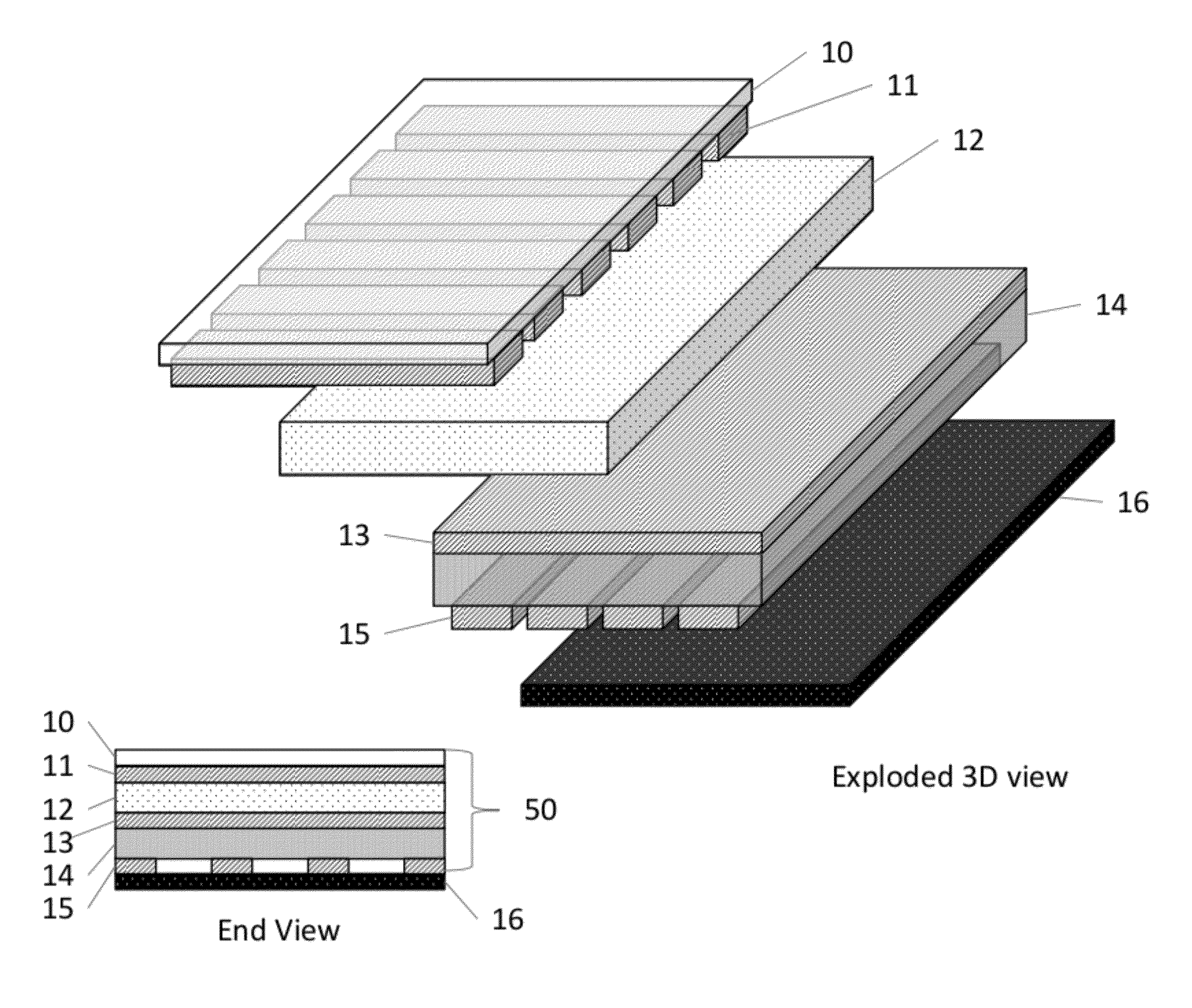
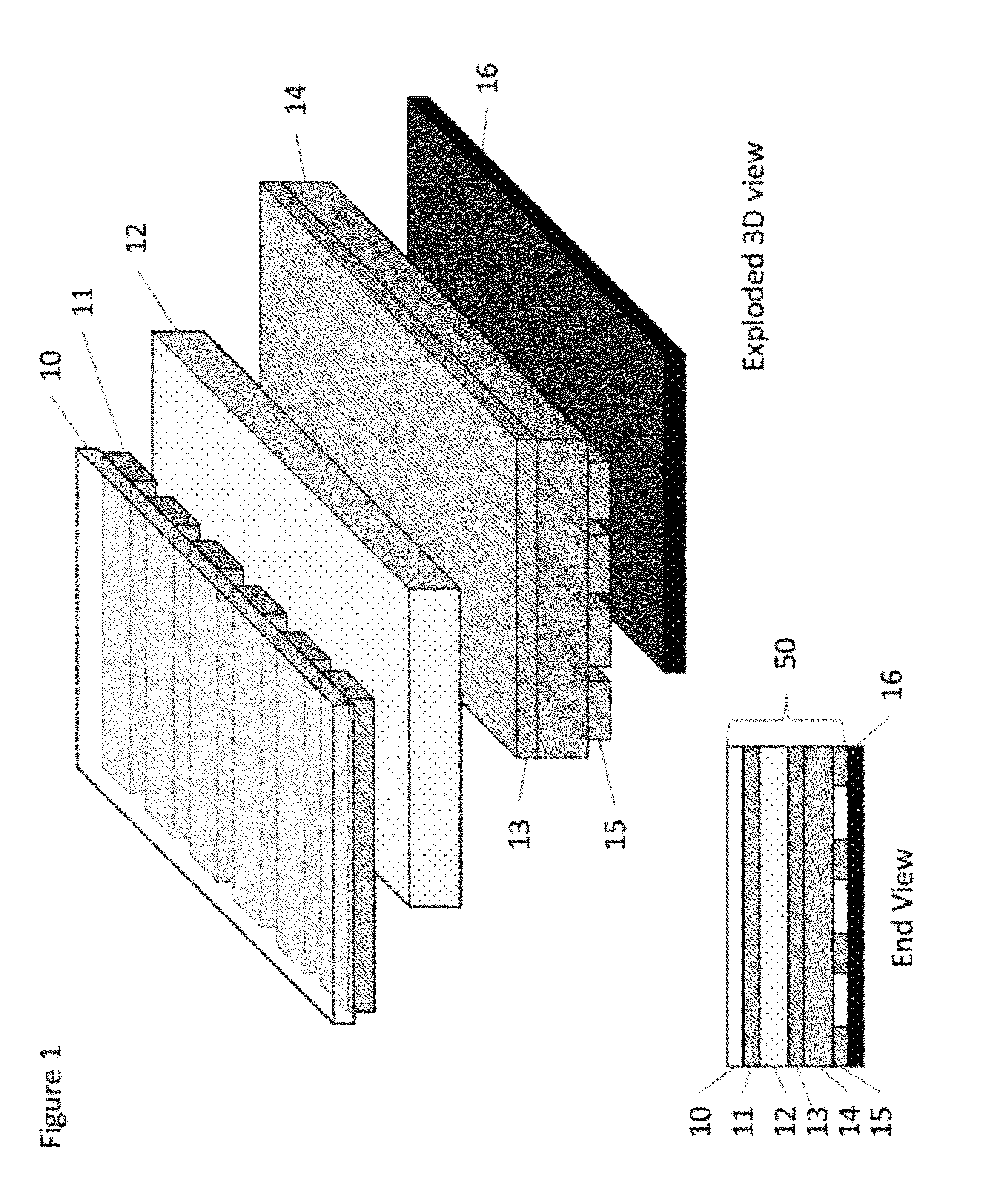
[0072]Embodiment 1a of the digital imaging device is shown in FIG. 1 where the columns of the piezoelectric film are selected and driven while the data is applied to the rows of the cholesteric layer. In this embodiment, a piezoelectric film 14 is used as one of the substrates for the cholesteric liquid crystal material 12. This embodiment is to take advantage of reduced threshold voltages provided by the cholesteric material during the time strain is induced by the piezoelectric layer. A discussion of the operation of a writing tablet that can be used in this disclosure is provided in the following paper, T. Schneider, G. Magyar, S. Barua, T. Ernst, N. Miller, S. Franklin, E. Montbach, D. Davis,...

Example

Example 2

Driving a Cholesteric Liquid Crystal Layer to the Planar Texture Using Ceramic Piezoelectric Particles

[0089]A Lead zirconate titanate (PZT) ceramic piezoelectric sensor was pulverized into a fine powder. Particles were filtered to remove large particles. Average particle size was less than 5 micrometers as measured by microscope. The particles were mixed with a polymeric binder and water mixture at 2:1 ratio of particles to binder by weight. The binder was composed of 50% water 30% polyvinyl alcohol 20% polyethylene glycol by weight.

[0090]A pressure sensitive display from a Boogie Board™ of Kent Displays, Inc. with 2 mil thick substrates was used for the cholesteric liquid crystal device. Graphite paint was applied in a 1 mm thick line to the backplane of the device as a conducting electrode. A 200 micron thick layer of PZT particles and binder was cast onto the graphite. A silver conductive paint was applied in a 1 mm thick line on the PZT particles and binder layer to for...

Example

Example 3

Driving a Cholesteric Liquid Crystal Layer to the Planar Texture Using a Ceramic Piezoelectric Post

[0092]A solid 0.254 mm thick flat PZT ceramic piezoelectric was painted with silver conducting paint on both sides and electrically connected to an amplifier and waveform generator. On top of the piezoelectric material, a small 1 mm wide plastic post was glued with cyanoacrylate (superglue). The top of the post was glued to the bottom of a supported cholesteric writing tablet display (the Boogie Board™).

[0093]The device was first driven to the focal conic texture by applying a voltage pulse (pushing the erase button) of the Boogie Board™ display. A 5 Hz square wave at 160V was then applied across silver electrodes producing a clearly visible planar texture in the writing tablet display in an area roughly 1 mm in diameter. The planar texture could be erased with the erase button of the Boogie Board™ and driven again to the planar texture with 5 Hz, 160 V square wave. When the d...


PUM

PropertyMeasurementUnit
Diameteraaaaaaaaaa
Diameteraaaaaaaaaa
Pressureaaaaaaaaaa

Abstract

A display device includes a piezoelectric layer. First electrically conductive electrodes are disposed on both sides of the piezoelectric layer. A bistable liquid crystal layer is disposed adjacent the piezoelectric layer. Second electrically conductive electrodes are disposed on both sides of the liquid crystal layer. The liquid crystal layer can be addressed by electrically addressing the piezoelectric layer causing the piezoelectric layer to move into contact with the liquid crystal layer, changing the brightness of pixels of the liquid crystal layer.

Description

TECHNICAL FIELD[0001]This disclosure pertains to a display device that includes piezoelectric and liquid crystal layers, wherein the liquid crystal layer can be addressed by pressure caused by electrically addressing the piezoelectric layer.BACKGROUND OF THE DISCLOSURE[0002]Cholesteric materials are known for their pressure sensitivity and are used for writing tablets; see U.S. Pat. No. 6,104,448. When a cholesteric material with a suitable pitch length is sandwiched between two substrates it can be made to exhibit two visibly different textures, a reflective planar texture that reflects colored light and a weakly light scattering focal conic texture that is transparent to the eye when the bottom substrate is adjacent to a dark background. If the upper substrate is flexible, the slight pressure of a pointed stylus applied to the substrate will locally reduce the spacing between the substrates inducing flow in the cholesteric liquid crystal, i.e., strain the cholesteric liquid crysta...

Claims


Application Information

Patent Timeline
IPC IPC(8): G02F1/1343G06F3/038G02F1/1347G02F1/1333G02F1/1334
CPCG02F1/13718G02F2001/13478G02F2001/133394G02F1/133394G02F1/13478
Inventor SCHNEIDER, TODMONTBACH, ERICADOANE, J. WILLIAMJAKLI, ANTALHARDEN, JOHN
Owner KENT STATE UNIV
Why Eureka
Try Eureka