Suture system

a suture system and valve technology, applied in the field of suture systems, can solve the problems of suture breakage, poor valve seating, peri-valvular leakage,

Inactive Publication Date: 2012-05-24
TELEFLEX MEDICAL INC +1
View PDF6 Cites 2 Cited by
  • Summary
  • Abstract
  • Description
  • Claims
  • Application Information

AI Technical Summary

Benefits of technology

[0007]In a preferred embodiment, the suture system of the present invention may contain several co-braided monofilament suture strands, where two strands of different colors, such as green and white, are co-braided into a single suture strand creating a third suture color or striped suture. This additional color suture provides differentiation between the other suture strands and acts as a visual indicator when tying off the sutures.
[0009]The suture system of the present invention results in a significant reduction and more particularly a reduction of between about forty to fifty percent (40-50%) in the number of needles and steps required to implant a prosthetic heart valve, and also reduces the time required for the procedure and the incidence of suturing errors. The suture system of the present invention provides many advantages to a surgeon. The surgeon can achieve proper spacing of the adjacent sutures which reduces the risk of peri-valvular leakage or interstitial bleeding that can occur as a result of using the interrupted sutures of the prior art. Further, there is a reduced risk for the needle to damage the adjacent suture as a result of trying to achieve the exact placement of the adjacent sutures that can occur with the interrupted suture technique. As the suture system of the present invention is provided with an alternating color such as a green and white suture strands and the option of using a third color suture positioned within the suture chain, confusion in determining which pairs of suture strands tie together is also substantially reduced. The spacing between two pledgets does not exceed 1-2 mm and more preferably, the pledgets are in abutting contact with each other.
[0012]Once the entire circumference of the valve annulus has been sutured, the prosthetic valve is sutured. The prosthetic is held approximately 5 cm above the valve annulus during suturing. The sutures are placed through the cuff of the prosthetic valve using first a single-armed or stranded needle to place the first suture and then using the double-stranded needles placed through the cuff so that the pairs of sutures are evenly spaced around the circumference of the cuff The prosthetic valve is aligned with the valve annulus. Once the sutures have been placed around the entire circumference of the cuff, the valve is lowered into position, the needles are cut off the sutures and the sutures are tied. The optional third color suture aids in tying off the sutures by acting as an additional visual indicator to differentiate between the suture strands associated with each pad or pledget. The prosthetic valve is then tested and the incision is closed.

Problems solved by technology

Peri-valvular leakage, when it occurs, is more commonly the result of an excessive distance separating two neighboring pledgets.
Although not always readily apparent at the time, this passing of one suture through the interstices of the adjacent strand may result in suture breakage when the sutures are tied, or in poor seating of the valve due to unevenly distributed tension.
As described above, every other stitch is technically more demanding and slightly more time consuming because of the increased precision required to pass extremely close to the preceding suture but without piercing it.
As space is often quite limited when working inside the heart, the entire exercise can be very demanding.

Method used


Image

  • Suture system
  • Suture system
  • Suture system

Examples


Embodiment Construction

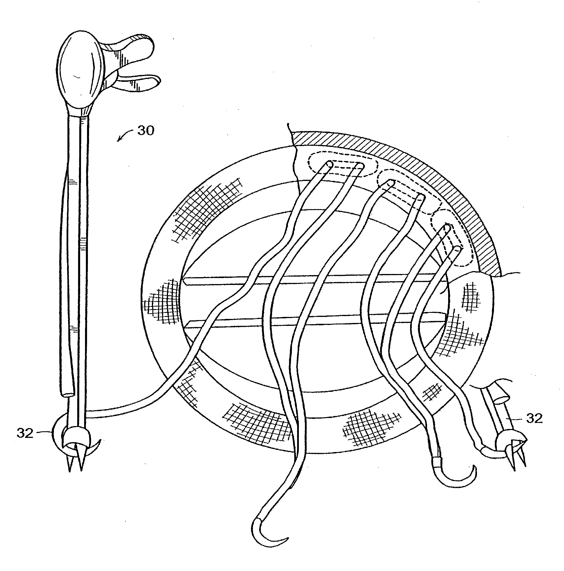
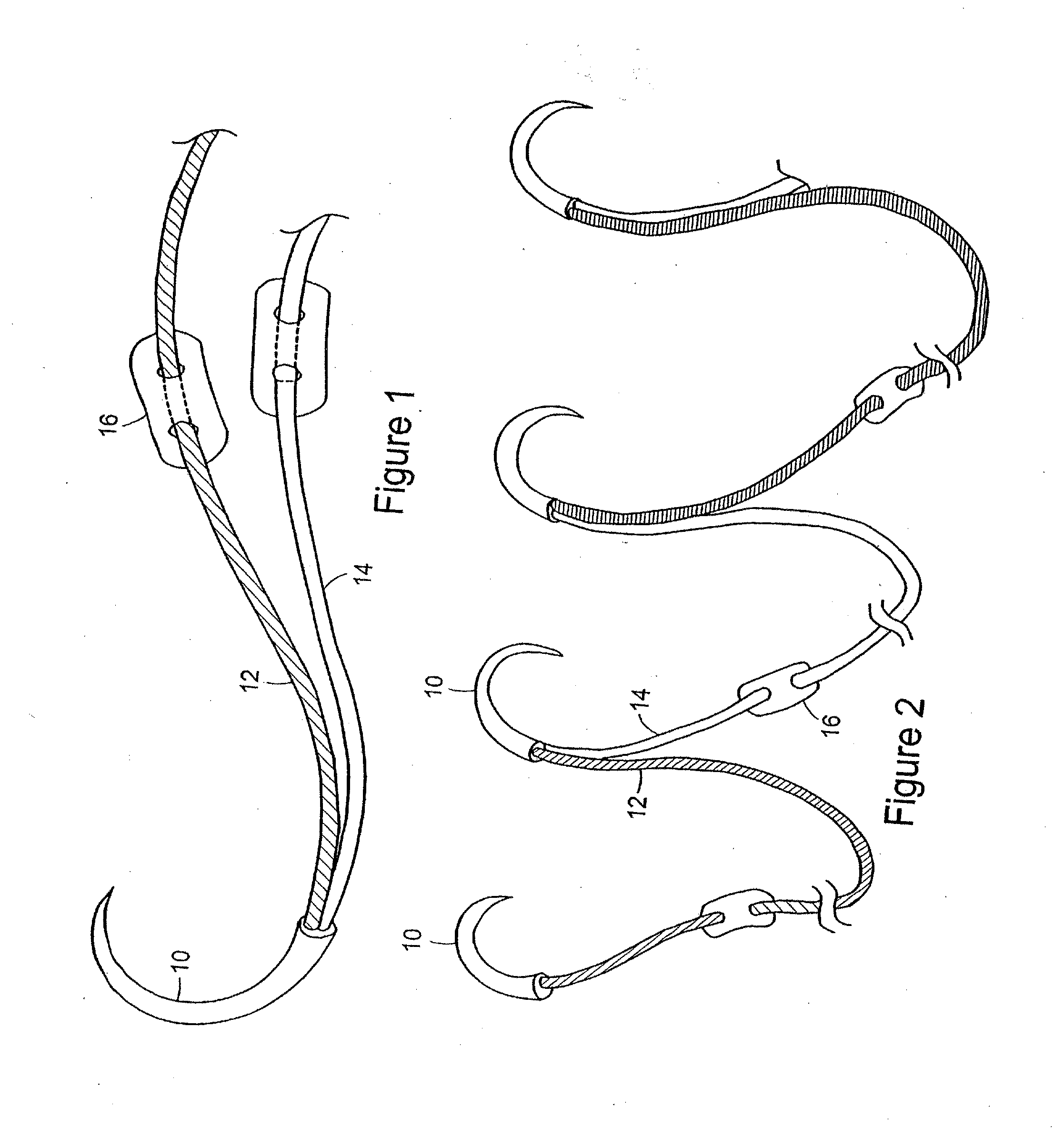
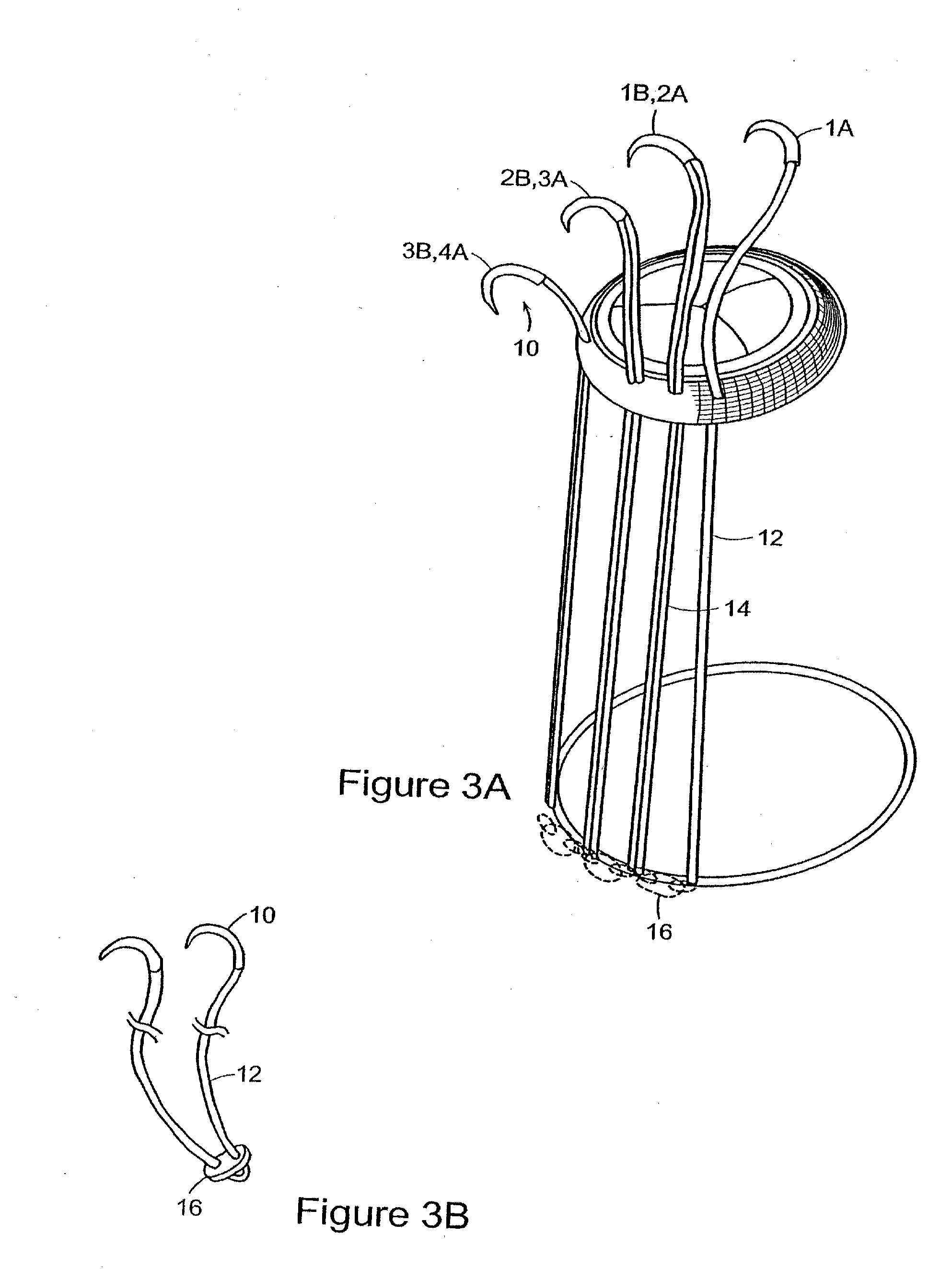
[0027]The present invention relates to a suture system for implanting valved prostheses. Valve implantation, such as cardiac valve implantation, consists of complex suturing process. This includes the placement of multiple mattress sutures in the tissue at the valve site, as well as to the suturing ring or cuff of the valve prostheses. This procedure is complicated by a very small working space inside the arteriotomy or aortotomy in order to excise the diseased native valve, then implant the prosthetic valve. In order to prevent perivalvular leakage and proper seating of the prosthetic valve, the surgeon normally places multiple (i.e., 14 or more) double-ended, pledgeted sutures in mattress or other configuration through both the in-situ annulus of the native, removed valve, and the suturing ring or cuff of the prosthetic valve. The suture strands are made of nonabsorbable polyester and are of a fixed length with a needle attached on both ends. The pledgets are made of PTFE or simil...


PUM


Abstract

A suture system includes a plurality of double-stranded needles connected in sequence with a single-stranded needle at each end. The double-stranded suture needles incorporates two suture strands into a single needle. The suture system of the present invention facilitates the implantation of valve prostheses.

Description

CROSS REFERENCES TO RELATED APPLICATIONS[0001]This application is a divisional of U.S. patent application Ser. No. 10 / 647,657 filed Aug. 25, 2003 now U.S. Pat. No. 8,097,005, which is a continuation of U.S. patent application Ser. No. 09 / 360,709 filed Jul. 26, 1999 now U.S. Pat. No. 6,610,071. The entire contents of the above applications are incorporated herein by reference.BACKGROUND OF THE INVENTION[0002]By far the most frequently used technique for implantation of prosthetic valves such as aortic and mitral valves is to use pledgeted mattress sutures. The term “mattress” refers to the fact that each suture passes through the fabric suturing ring or cuff of the prosthetic valve and through the tissue to which the prosthesis will be attached at two points separated, for example, by a gap of about 4 to 8 mm and more preferably between about 4 to 6 nun. To facilitate this, the piece of suture material has two surgical needles pre-attached, one at each end. The term “suture” refers t...

Claims


Application Information

Patent Timeline
Patent Type & Authority Applications(United States)
IPC IPC(8): A61B17/04A61B17/00A61B17/06A61B19/00A61F2/24
CPCA61B17/06166A61B2017/00243A61B2017/00783A61B2017/047A61F2/2427A61B2017/06028A61B2017/06057A61B2019/444A61F2/2409A61B2017/0472A61B90/92
Inventor COHN, WILLIAMMATHERS, THOMAS P.
Owner TELEFLEX MEDICAL INC
Why Eureka
Try Eureka