Stent with protected barbs

a technology of stents and barbs, applied in the field of medical devices, can solve the problems of increasing the operating effort of removing the sheath from the device, and achieve the effect of improving the barb arrangement of implantable medical devices and improving the method and system for deploying implantable devices

Active Publication Date: 2012-05-24
COOK MEDICAL TECH LLC
View PDF11 Cites 65 Cited by
  • Summary
  • Abstract
  • Description
  • Claims
  • Application Information

AI Technical Summary

Benefits of technology

[0005]The present invention seeks to provide an improved implantable medical device provided with barbs, an improved barb arrangement for implantable medical devices and an improved method and system for deploying implantable medical devices.

Problems solved by technology

Such frictional engagement may result in increased operating effort to remove the sheath from the device.

Method used


Image

  • Stent with protected barbs
  • Stent with protected barbs
  • Stent with protected barbs

Examples


Embodiment Construction

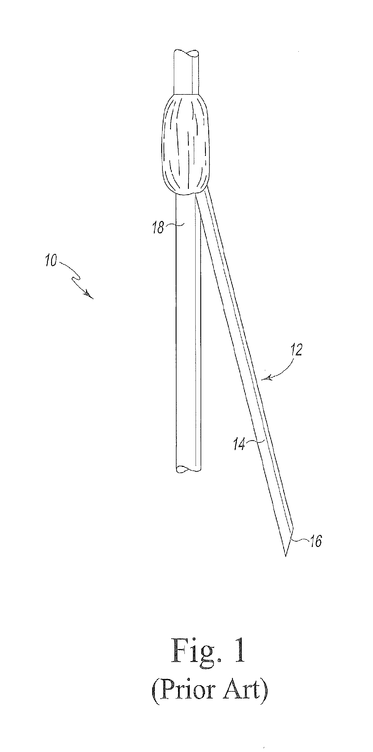
[0033]FIG. 1 depicts a prior art stent 10 with a barb 12. The barb 12 has a barb body 14 that extends distally towards a barb tip 16. The tip 16 is preferably sharp and, when the stent is inserted into a vessel, can engage the vessel to limit movement of the stent within the vessel. In this example, the barb 12 is fixedly attached to a strut 18 of the stent 10 via weld, solder, adhesive or the like. In other examples, the barb 12 and the stent 10 may be monolithic. In other examples, the barb 12 may be variably, rather than fixedly, attached to the stent. Examples of barbs and attachment techniques are disclosed, for example, in U.S. Pub. Pat. App. Nos. 2003 / 0236570 A1 and 2005 / 0240259 A1. Each of these references is herein incorporated by reference.

[0034]The barb of FIG. 1 is shown in an extended configuration. The distal tip 16 extends outwardly from the stent 10 in this configuration. The distal tip 16 is unprotected and may engage tissue of a vessel in which the stent 10 is plac...


PUM

PropertyMeasurementUnit
temperaturesaaaaaaaaaa
strengthaaaaaaaaaa

Abstract

An endoluminal prosthesis is described and comprises a stent (40), At least one barb (42) secured to the stent, and a degradable barb guard (52) covering at least a portion of the barb and protecting the distal tip when the stent is in a compressed configuration. The barb guard (52) comprises a degradable structure that degrades to expose the distal tip of the barb when the stent is placed in a vessel. An endoluminal prosthesis deployment system comprising a sheath having a lumen and a prostesis within the sheath lumen is also described

Description

TECHNICAL FIELD[0001]This invention relates to medical devices and, in particular, to devices, systems, and methods for anchoring a prosthesis such as an implantable medical device in a body lumen.BACKGROUND ART[0002]Deploying an endoluminal prosthesis into the vessel of a patient from a remote location is generally known. An endoluminal prosthesis, such as a stent or stent graft, is introduced into a vessel in a radially constrained state. Once the prosthesis is positioned, it can then be expanded within the vessel. The prosthesis may employ one or more barbs that can engage the vessel wall to limit movement of the prosthesis within the vessel.[0003]An endoluminal prosthesis is typically introduced into a vessel via a delivery and deployment device. Such a device may include a cover or sheath that is placed within the vessel. The prosthesis is manipulated within the sheath into the vessel. The sheath is retracted from the prosthesis to allow the prosthesis to expand within the vess...

Claims


Application Information

Patent Timeline
Patent Type & Authority Applications(United States)
IPC IPC(8): A61F2/84A61F2/82A61F2/86
CPCA61F2/86A61F2/95A61F2220/0016A61F2210/0004A61F2250/0071A61F2002/8483A61F2/848
Inventor AGNEW, CARLBOWE, JASONDIERKING, KURTKRATZBERG, JARINLEEWOOD, ALANORR, DAVID
Owner COOK MEDICAL TECH LLC
Why Eureka
Try Eureka