Microheater and microheater array

a micro-heater and array technology, applied in the field of micro-heaters, can solve the problems of difficult to maintain a desired temperature range, high temperature difference based on location, and increase of driving voltage, and achieve the effect of uniform temperature distribution

Inactive Publication Date: 2012-05-31
SAMSUNG ELECTRONICS CO LTD
View PDF2 Cites 206 Cited by
  • Summary
  • Abstract
  • Description
  • Claims
  • Application Information

AI Technical Summary

Benefits of technology

[0008]One or more exemplary embodiments provide a microheater having a small internal

Problems solved by technology

Thus, in such a microheater, temperature differences difference based on location may be high.
In a case in which such a tem

Method used


Image

  • Microheater and microheater array
  • Microheater and microheater array
  • Microheater and microheater array

Examples


Embodiment Construction

[0024]Reference will now be made in detail to exemplary embodiments with reference to the accompanying drawings. In the drawings, the thicknesses of layers and regions may be exaggerated for clarity of the description.

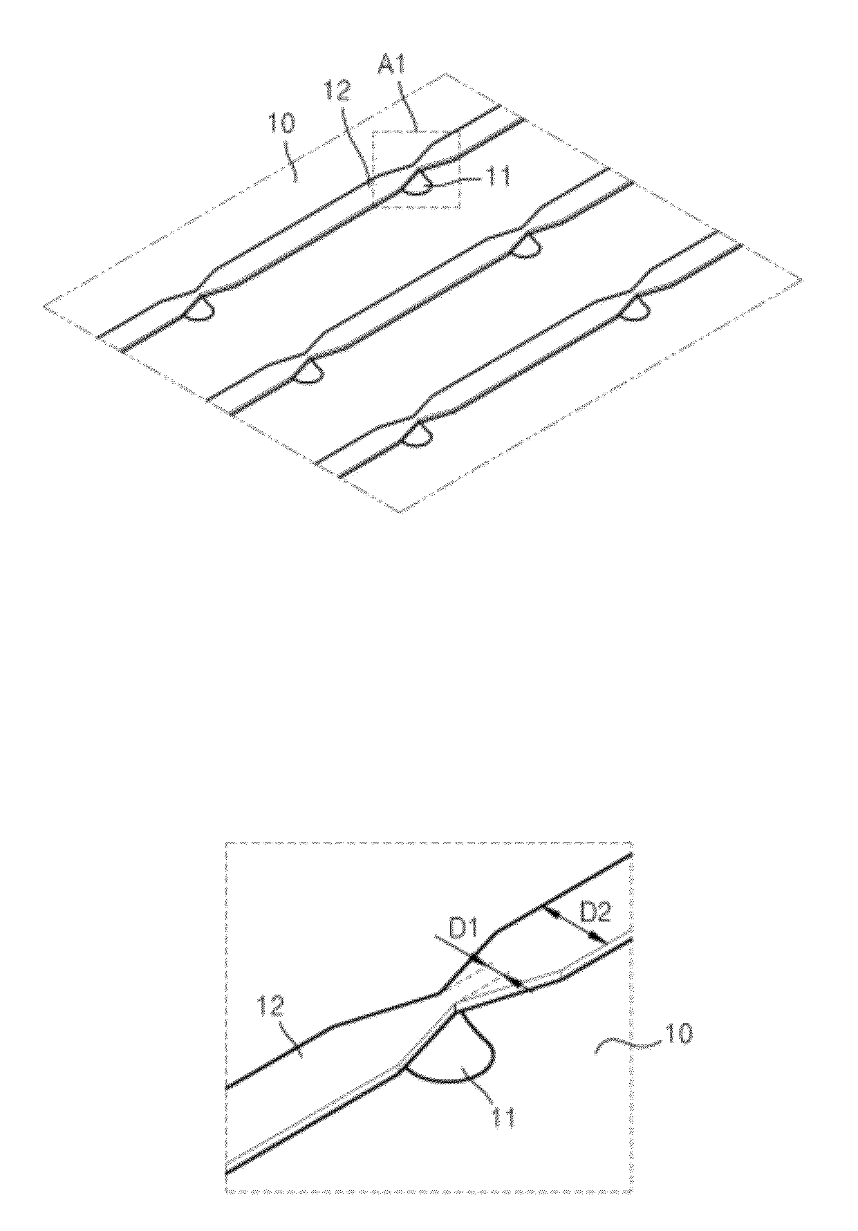
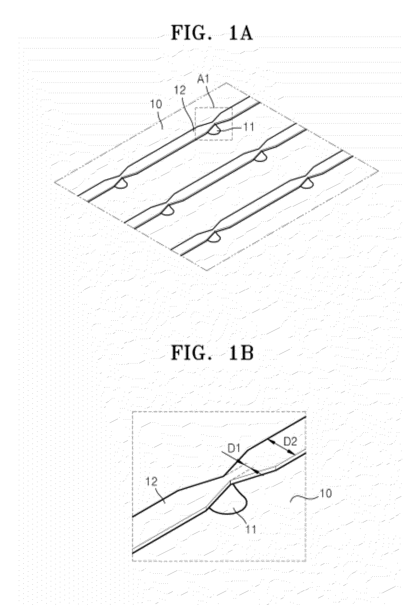
[0025]FIG. 1A is a perspective view of a microheater according to an exemplary embodiment.

[0026]Referring to FIG. 1A, a column 11 is formed on a substrate 10, and a bridge 12 is formed on the column 11. The bridge 12 may be supported by the column 11 and may be spaced apart from the substrate 10. A plurality of the columns 11 may be formed on the substrate 10, and a plurality of the bridges 12 may be supported by the columns 11 and may be formed in parallel, forming an array. A distance between the substrate 10 and the bridge 12 may be selected according to the particular application, and arrangements other than the parallel formation shown in FIG. 1A may be used. For example, the bridges 12 may intersect or may be disposed one over another by adjusting heights of the ...


PUM


Abstract

A microheater and a microheater array are provided. The microheater includes a substrate, a column disposed on the substrate and a bridge supported by the column. A width of a portion of a bridge formed on the column is less than a width of a portion of the bridge that does not contact the column. The bridge may include a spring component.

Description

CROSS-REFERENCE TO RELATED APPLICATION[0001]This application claims priority from Korean Patent Application No. 10-2010-0119787, filed on Nov. 29, 2010, in the Korean Intellectual Property Office, the disclosure of which is incorporated herein by reference in its entirety.BACKGROUND[0002]1. Field[0003]Apparatuses and methods consistent with exemplary embodiments relate to a microheater, and more particularly, to a microheater and a structure of a microheater array in which a width of a connection part between microheaters is adjusted so that the microheater array generally has a uniform temperature distribution, and to a manufacturing method thereof.[0004]2. Description of the Related Art[0005]A microheater is a device for locally generating heat at a desired position on a substrate. Microheaters may be used in electronic devices such as carbon nanotube transistors, polycrystalline silicon thin-film transistors, or the like, or solar cells, which utilize high temperature processes.[...

Claims


Application Information

Patent Timeline
IPC IPC(8): H05B3/02
CPCH05B3/265H05B2214/04H05B2203/012
Inventor CHOI, JUN-HEELEE, JOO-HOSONG, MI-JEONG
Owner SAMSUNG ELECTRONICS CO LTD
Why Eureka
Try Eureka