transformer

a transformer and transformer technology, applied in transformers/inductance details, transformers/inductance coils/windings/connections, electrical apparatus, etc., can solve the problems of eddy current, mounting failure, deterioration of the surroundings of the electrode connecting portion, etc., to improve the dc superposition characteristic, reduce the stray capacitance, and stabilize the output voltage

Active Publication Date: 2012-05-31
TDK CORPARATION
View PDF8 Cites 53 Cited by
  • Summary
  • Abstract
  • Description
  • Claims
  • Application Information

AI Technical Summary

Benefits of technology

[0021]The present invention can provide a transformer which can improve the DC superposition characteristic without incurring eddy-current losses. The present invention can also provide a step-up transformer which can reduce the stray capacitance and stabilize the output voltage.

Problems solved by technology

During thermocompression bonding of winding terminals to the electrodes in transformers constructed basically as mentioned above, the heat of thermocompression bonding may deteriorate the surroundings of the electrode connecting portions.
Thus deteriorated parts may cause mounting failures when included in a surface to be mounted on a substrate.
In a simple flat structure such as that of the conventional plate-like core, however, a magnetic flux may pass between the plate-like core and the terminal electrode, thereby causing an eddy current, which produces an eddy-current loss.
However, this may increase the stray capacitance between the first and secondary windings depending on the positional relationship between the winding start portions of the primary and secondary windings.
In particular, when the stray capacitance between the higher voltage side of the secondary winding (the winding start side of the secondary winding) and the primary winding increases, the LC resonance may be so high that the output voltage of the transformer becomes unstable, thereby generating ringing.
Hence, how to wind the primary and secondary windings about the winding core part has become an important problem.

Method used


Image

  • transformer
  • transformer
  • transformer

Examples


second embodiment

[0063]The step-up transformer in accordance with the present invention will now be explained.

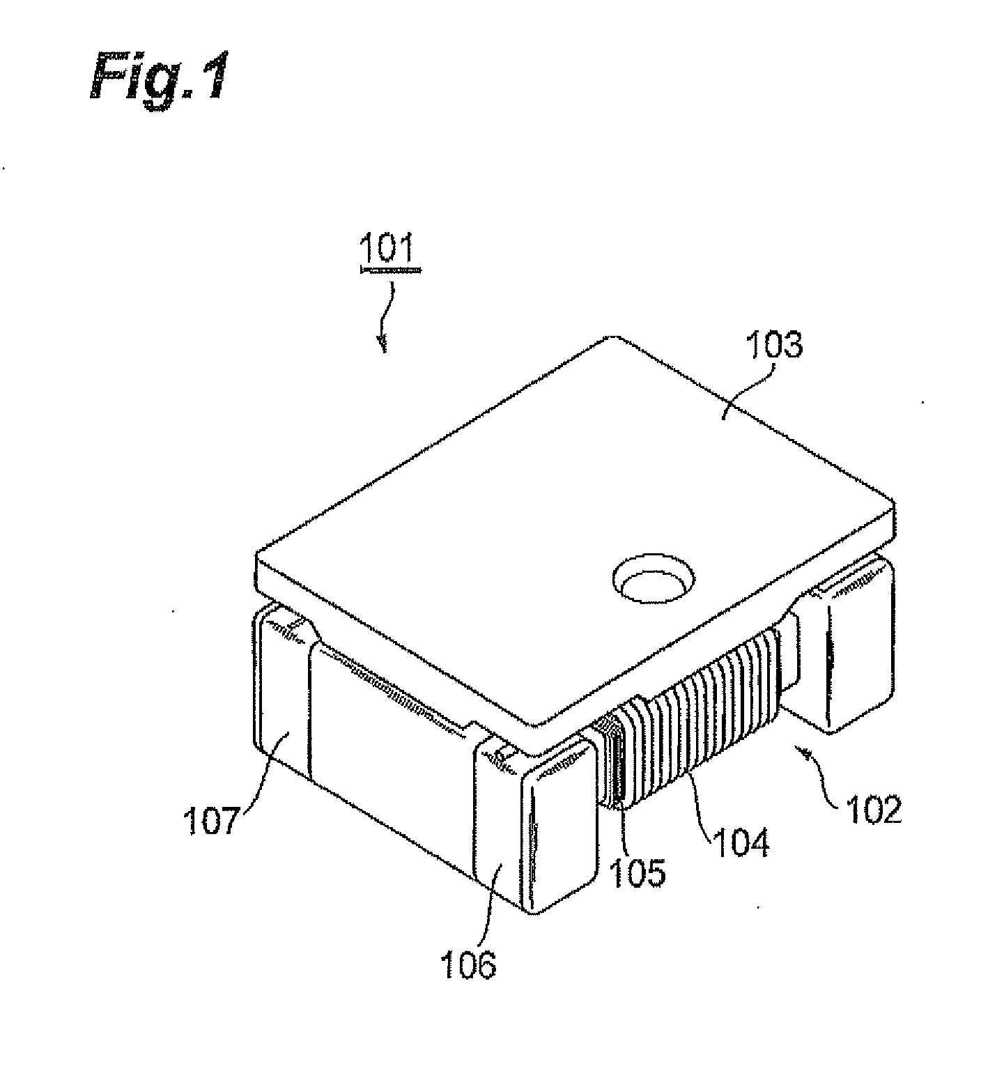
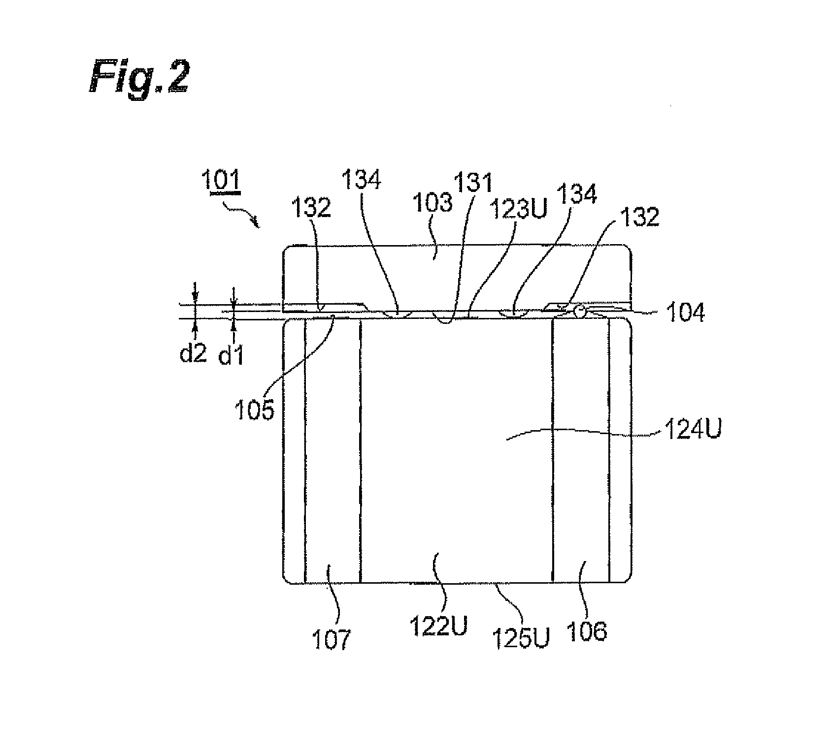
[0064]FIGS. 10 to 14 are perspective, front, side, top plan, and bottom plan views of the step-up transformer in accordance with the second embodiment, respectively, while FIGS. 15 to 18 are front, side, top plan, and bottom plan views illustrating the step-up transformer without its plate-like core. FIG. 19 is a circuit diagram of the drum core in accordance with an example.

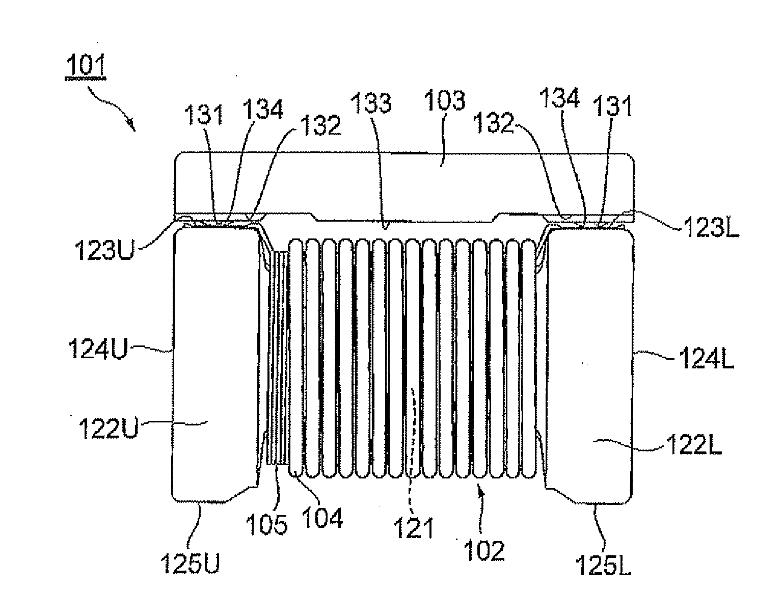
[0065]The step-up transformer 201A in accordance with this embodiment is used for stepping up the voltage of a strobe light source for a camera, for example, and comprises a drum core 202, a primary winding 203, a secondary winding 204, input terminals 205U, 205L, output terminals 206U, 206L, and a plate-like core 207 as illustrated in FIGS. 10 to 14. Here, the step-up transformer 201A has a length (in the horizontal direction in FIG. 13) of about 3.2 mm, a width (in the vertical direction in FIG. 13) of about 2.5 mm, an...

third embodiment

[0078]The step-up transformer in accordance with the present invention will now be explained.

[0079]FIG. 22 is a sectional view illustrating a main part of the step-up transformer in accordance with the third embodiment of the present invention. This step-up transformer 201B is one in which the primary and secondary windings 203, 204 are wound differently from those in the step-up transformer 201A in accordance with the second embodiment illustrated in FIG. 20.

[0080]In the step-up transformer 201B, the start wire S2 is located at a position adjacent to the flange 222U, each tier of the secondary winding 204 is wound from the flange 222U on one side to the flange 222L on the other side, and the winding end portion of the secondary winding 204 is not directly wound about the winding core part 221.

[0081]In the step-up transformer 201B, the number of turns of the primary winding 203 is smaller than that in the step-up transformer 201A in accordance with the second embodiment, while the w...

fourth embodiment

[0086]The step-up transformer in accordance with the present invention will now be explained.

[0087]FIG. 23 is a sectional view illustrating a main part of the step-up transformer in accordance with the fourth embodiment of the present invention. This step-up transformer 201C is one in which the primary winding 203 is wound differently from that in the step-up transformer 201B in accordance with the third embodiment illustrated in FIG. 22. That is, in the step-up transformer 201C, the winding start portion S1 of the primary winding 203 is located at a position adjacent to the flange 222U on one side, while the primary winding 203 is wound at substantially uniform intervals such that its turns are in no contact with each other.

[0088]In thus constructed step-up transformer 201C, as in the step-up transformer 201A in accordance with the second embodiment, the start wire S2, which is the winding start portion of the secondary winding 204 for the winding core part 221, is covered with the...


PUM

PropertyMeasurementUnit
thicknessaaaaaaaaaa
heightaaaaaaaaaa
heightaaaaaaaaaa

Abstract

A transformer that improves the DC superposition characteristic without incurring eddy-current losses. In the transformer, a part of a plate-like core opposing a top face of a flange of a drum core is formed with a first opposing portion opposing none of input and output terminals and a second opposing portion opposing the input and output terminals. A first gap is formed between the top face and the first opposing portion by a spacer. A second gap greater than the first gap is formed by a recess of the plate-like core provided so as to correspond to the second opposing portion. This allows magnetic fluxes to pass between the top face and the first opposing portion where the gap is formed and inhibits them from passing between the plate-like core and the input and output terminals where the second gap greater than the first gap is formed.

Description

BACKGROUND OF THE INVENTION[0001]1. Field of the Invention[0002]The present invention relates to a transformer.[0003]2. Related Background Art[0004]The balun transformer disclosed in Japanese Patent Application Laid-Open No, 10-326715 has conventionally been known as an example of transformers for use in small electronic devices and the like. This type of conventional transformer is constructed by joining a flat core to a drum-shaped core having a center flange and quadrangular end flanges at both ends. Two windings (primary and secondary windings) are wound, for example, one by one as lower and upper tiers, about each winding groove (winding core part) formed between the center flange and the end flanges, Electrodes are disposed on side faces of the flanges, while terminals of the windings are connected to their corresponding electrodes.SUMMARY OF THE INVENTION[0005]During thermocompression bonding of winding terminals to the electrodes in transformers constructed basically as ment...

Claims


Application Information

Patent Timeline
Patent Type & Authority Applications(United States)
IPC IPC(8): H01F27/29
CPCH01F27/292H01F3/14
Inventor TOMONARI, TOSHIOHARATA, HIDEAKITSUCHIDA, SETUKAWAHARA, KEISUKE
Owner TDK CORPARATION
Why Eureka
Try Eureka