Dental positioning stent, and manufacturing method, using method and components for the same

a manufacturing method and technology for dental implants, applied in dental surgery, instruments, applications, etc., can solve the problems of difficult for dentists to transform into physical tooth molds, harming neighboring teeth or nerves, and difficulty in evaluating tooth implant surgery

Inactive Publication Date: 2012-05-31
CHENG PO KUN +3
View PDF6 Cites 59 Cited by
  • Summary
  • Abstract
  • Description
  • Claims
  • Application Information

AI Technical Summary

Benefits of technology

[0009]Accordingly, a major objective of embodiments of the disclosure is to provide a dental positioning stent and a manufacturing method for the same, so as to aid tooth implant positioning, and help a dentist to evaluate tooth implant surgery accurately according to a tomography image and a tooth mold.
[0010]Another objective of the embodiments of the disclosure is to provide a dental positioning stent and a manufacturing method for the same, to take a tooth tomography scanning slice image and aiding a dentist to acquire an accurate slice image.

Problems solved by technology

If only personal experiences are relied on, and no reliable aiding tools are available, an error may be incurred to an implant position, thereby harming neighboring teeth or nerves.
In fact, errors may still occur, thereby incurring risks of harming neighboring teeth or nerves.
However, the tooth implant position is analyzed through a computer, the analysis of which is difficult for the dentist to transform into a physical tooth mold, and is likely to result in error when in a tooth implant position of the guide seat a2 is transformed.
In addition, the 3D image analysis software and the guide seat machining table are typically too costly to implement.
More importantly, tooth implant evaluation cannot be performed according to a shape of a false tooth expected to be mounted and a gum image at the same time, and the tooth implant position and a tooth implant angle can only be analyzed according to the gum image, which may cause the implant to be inconsistent with adjacent teeth.

Method used


Image

  • Dental positioning stent, and manufacturing method, using method and components for the same
  • Dental positioning stent, and manufacturing method, using method and components for the same
  • Dental positioning stent, and manufacturing method, using method and components for the same

Examples


first embodiment

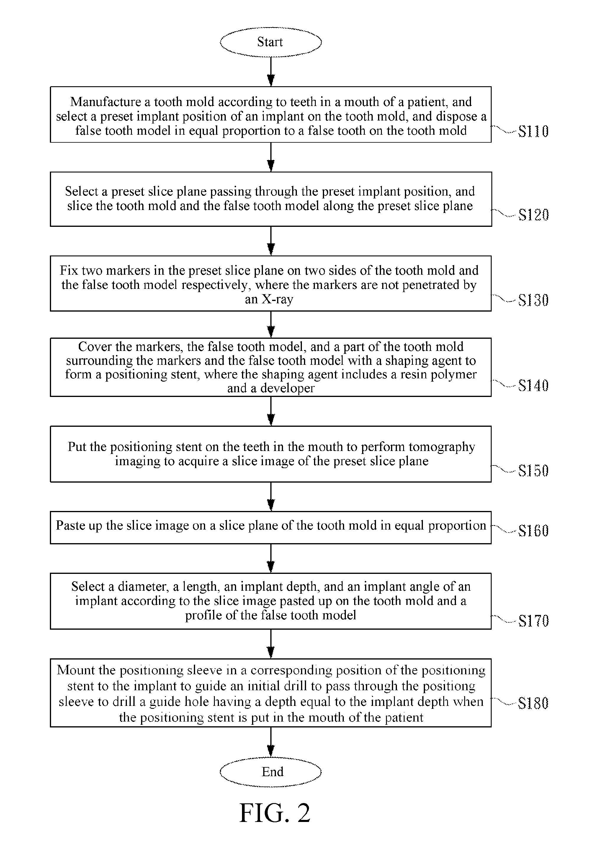
[0051]Please refer to FIG. 2, is a flowchart according to a A dental positioning stent and a manufacturing method thereof provided by the disclosure are used for positioning an implant to mount a false tooth on the implant. The manufacturing method includes the following steps.

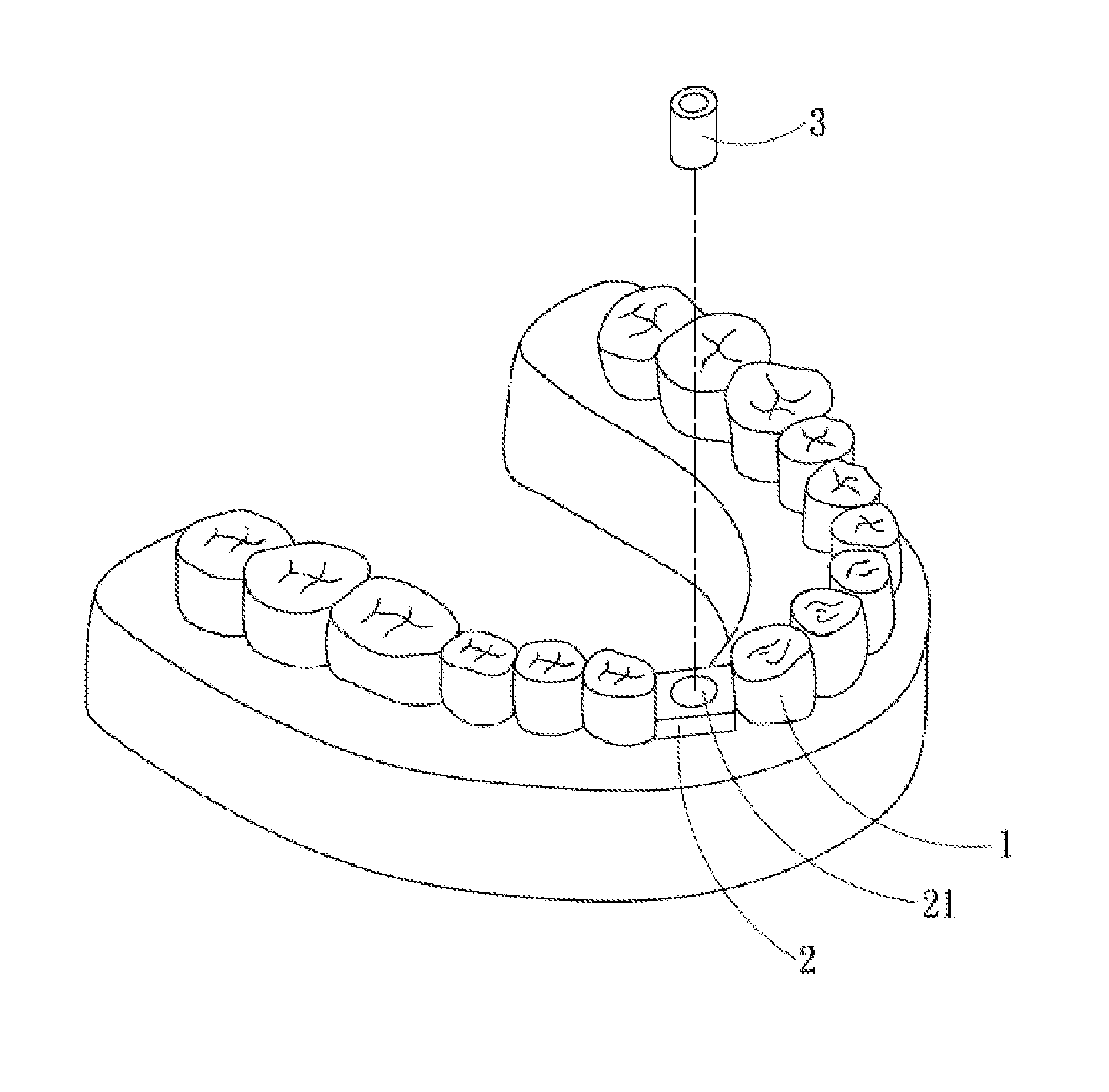
[0052]In Step S110, a tooth mold is manufactured according to teeth in a mouth of a patient, and a preset implant position of an implant on the tooth mold is selected, according to which a false tooth model in equal proportion to a false tooth is disposed on the tooth mold.

[0053]Please refer to FIG. 3, is a model diagram according to the first embodiment. A tooth mold 1 is manufactured by rolling over according to teeth in a mouth of a patient, a false tooth model 12 in equal proportion to a false tooth expected to be mount is manufactured, and the false tooth model 12 is disposed on the tooth mold 1. A center of the false tooth model 12 is a preset implant position 13 of an implant.

[0054]Please refer to FIG....

second embodiment

[0088]Please refer to FIG. 12. FIG. 12 is a schematic view of a guide drill according to the Before using the enlargement drill 8, a guide drill 9 may be used to ream an upper end of the guide hole 15. The guide drill 9 is like the enlargement drill 8 to have a cutting portion 91 and a shank portion 92, and have a cylindrical portion 93 extending from a top of the cutting portion 91. A top of the cylindrical portion 93 is flat. Thus, after the cylindrical portion 93 is placed in advance into the guide hole 15 drilled in Step S180, the cutting portion 91 reams downwards the upper end of the guide hole 15.

[0089]Then, the enlargement drill 8 is used to continue to perform reaming downwards according to a part reamed by the guide drill 9, so as to ream the guide hole 15 more steady and more accurately to form the implant hole 19.

[0090]Please refer to FIG. 13A and FIG. 13B. FIG. 13A is a schematic view of reaming according to a third embodiment, and FIG. 13B is a schematic view of an en...

third embodiment

[0107]Please refer to FIG. 12. FIG. 12 is a schematic view of the guide drill according to the Before using the enlargement drill 8, the guide drill 9 may be used to pass through the positioning hole 21 of the positioning aid 2 to ream the upper end of the guide hole 15. The guide drill 9 has the cutting portion 91 and the shank portion 92 the same as those of the enlargement drill 8, and has the cylindrical portion 93 extending from the top of the cutting portion 91. The top of the cylindrical portion 93 is flat. Thus, after the cylindrical portion 93 is placed in advance into the guide hole 15 drilled in Step S180, the cutting portion 91 reams downwards the upper end of the guide hole 15. Here, as in the manner in which the enlargement drill 8 cooperates with the positioning cap 5, a shank head portion 921 of the guide drill 9 is placed in the tube portion 51 of the positioning cap 5.

[0108]Next, the enlargement drill 8 is used to continue to perform reaming downwards according to...


PUM


Abstract

A dental positioning stent for drilling an implant hole and a manufacturing method, a using method and components for the same are provided. The manufacturing method includes: slicing a tooth mold and a false tooth model along a preset slice plane; fixing two markers in the preset slice plane on two sides of the false tooth model respectively; covering the markers and the false tooth model with a shaping agent to form a positioning stent; putting the positioning stent on the teeth in a mouth to perform tomography imaging to acquire a slice image of the preset slice plane; mounting a positioning aid having a positioning hole in the positioning stent according to the slice image pasted up on the tooth mold to guide an initial drill. A dental positioning stent for tomography imaging, and a manufacturing method, a using method, and components thereof are provided.

Description

CROSS-REFERENCES TO RELATED APPLICATIONS[0001]This non-provisional application claims priority under 35 U.S.C. §119(a) on Patent Application No. 99140979 filed in Taiwan, R.O.C. on 2010 Nov. 26, the entire contents of which are hereby incorporated by reference.BACKGROUND[0002]1. Technical Field[0003]The disclosure relates to a dental positioning stent, and a manufacturing method, a using method, and components for the same, and more particularly to a dental positioning stent for positioning an implant and to take tooth tomography scanning slice images, and a manufacturing method, a using method, and components for the same.[0004]2. Related Art[0005]Before performing tooth implant surgery, a dentist normally makes a tooth mold according to the teeth of a patient, and determines a tooth implant position, and an implant angle and an implant depth of an implant on the tooth mold according to experiences. However, for patients, tooth structures are all different, and growth directions of...

Claims


Application Information

Patent Timeline
Patent Type & Authority Applications(United States)
IPC IPC(8): A61C8/00A61C19/00A61C13/34A61C3/00
CPCA61C1/084A61C8/0089A61B6/02A61C13/34A61C8/0051A61C13/08A61B6/14A61C3/02A61C8/00A61C13/1016A61C19/04
Inventor CHENG, PO-KUNCHENG, CHIA-YUNCHENG, CHIA-YUCHENG, CHAO-HSIANG
Owner CHENG PO KUN
Why Eureka
Try Eureka