Methods and Apparatus for Suspension Adjustment

a technology of suspension adjustment and method, which is applied in the field of vehicle suspension, can solve the problems of many current systems relying on imprecise tools and methods, and may be difficult to adjust the spring mechanism to the correct pres

Active Publication Date: 2012-05-31
FOX FACTORY
View PDF13 Cites 73 Cited by
  • Summary
  • Abstract
  • Description
  • Claims
  • Application Information

AI Technical Summary

Problems solved by technology

One disadvantage with conventional shock absorbers is that adjusting the spring mechanism to the correct preset may be diffi...

Method used


Image

  • Methods and Apparatus for Suspension Adjustment
  • Methods and Apparatus for Suspension Adjustment
  • Methods and Apparatus for Suspension Adjustment

Examples


Embodiment Construction

[0023]This patent application is related to U.S. patent application Ser. No. 12 / 773,671; U.S. Provisional Patent Application Ser. No. 61 / 175,422 (“'422”); U.S. Provisional Patent Application Ser. No. 61 / 302,070; and U.S. Provisional Patent Application Ser. No. 61 / 411,901; each of which is entirely incorporated herein by reference. Any individual feature or combination of the features disclosed in the foregoing incorporated references may be suitable for combination with embodiments of this present disclosure.

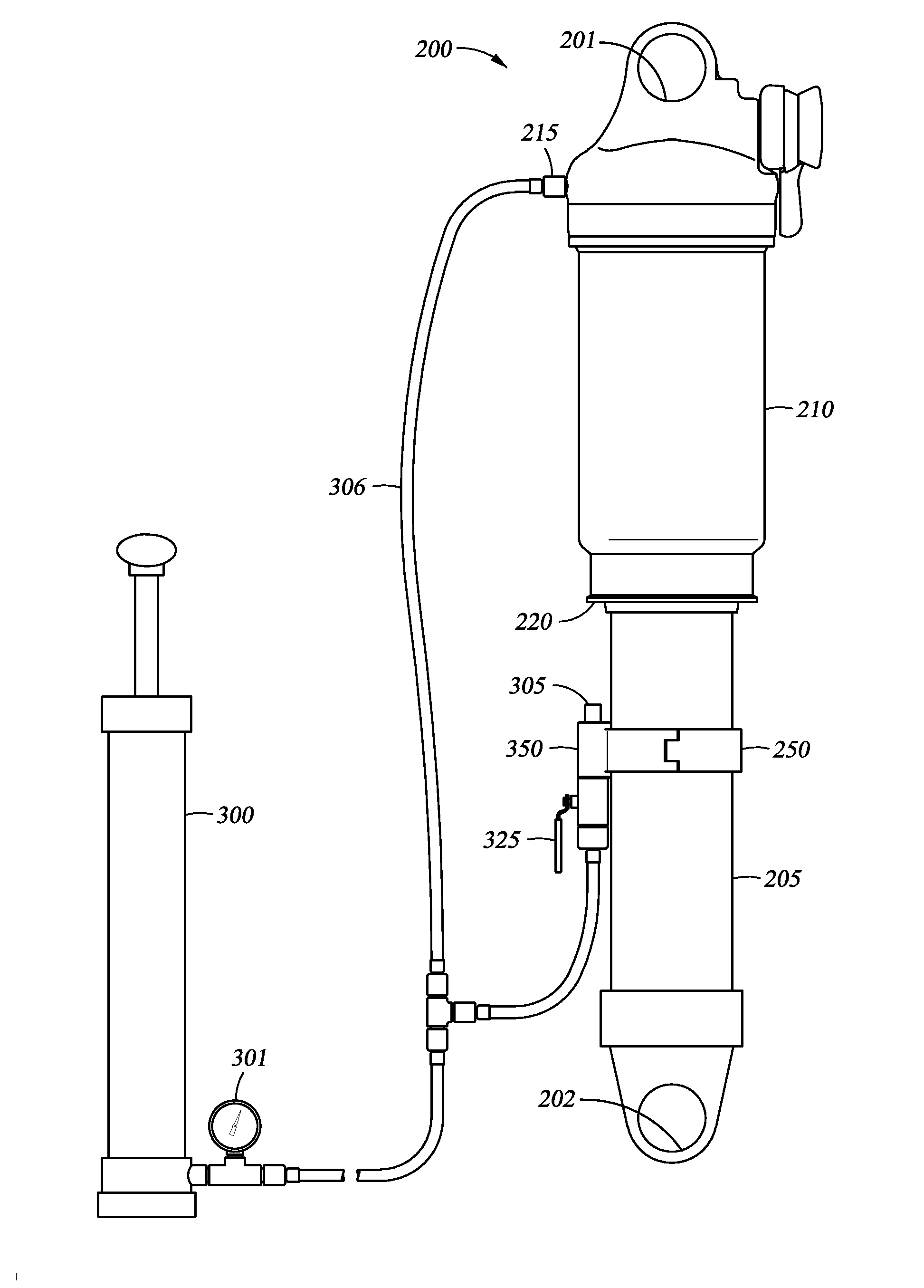
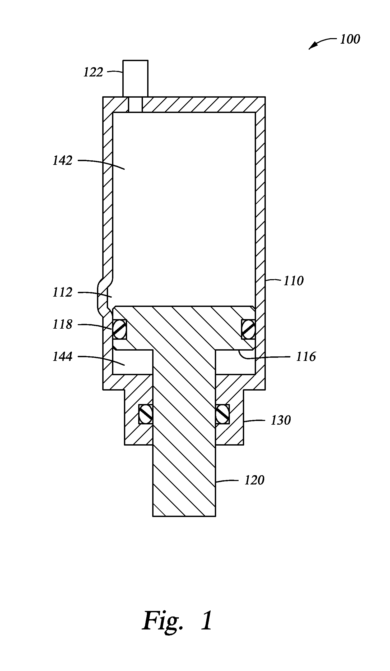
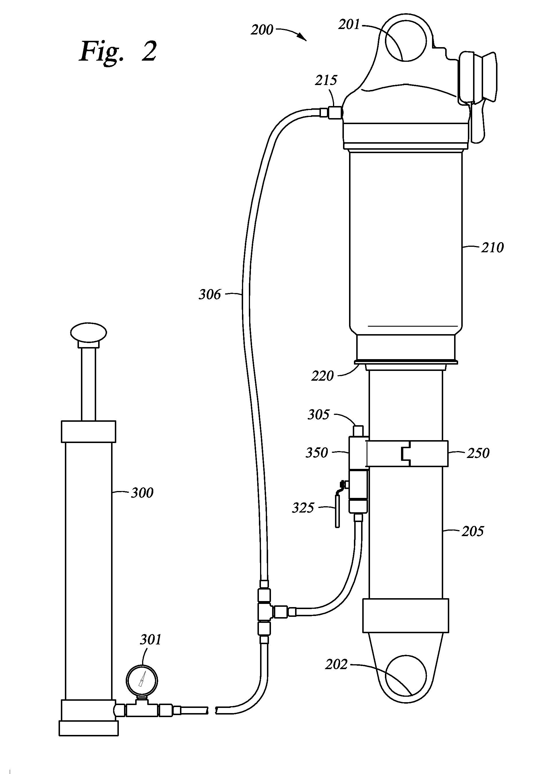
[0024]Integrated damper / spring vehicle shock absorbers often include a damper body surrounded by a mechanical spring. The damper often consists of a piston and shaft telescopically mounted in a fluid filled cylinder. The mechanical spring may be a helically wound spring that surrounds the damper body. Various integrated shock absorber configurations are described in U.S. Pat. Nos. 5,044,614; 5,803,443; 5,553,836; and 7,293,764; each of which is herein incorporated, in its entire...


PUM


Abstract

A shock absorber includes a gas spring cylinder containing a piston moveable between an extended position and a compressed position within the gas spring cylinder. A mechanical actuator is arranged whereby a bleed port is automatically closed when the gas spring is compressed to a predetermined position corresponding to a desired sag setting. In one embodiment, the position corresponds to a predetermined sag setting whereby the gas spring is partially compressed. In another embodiment, a proper sag setting is determined through the use of a processor and sensor that in one instance measure a position of shock absorber components to dictate a proper sag setting and in another instance calculate a pressure corresponding to a preferred sag setting.

Description

CROSS-REFERENCE TO RELATED APPLICATIONS[0001]This application claims benefit of U.S. Provisional Patent Application Ser. No. 61 / 427,438 (Atty. Dkt. No. FOXF / 0053USL), filed Dec. 27, 2010, and claims benefit of U.S. Provisional Patent Application Ser. No. 61 / 533,712 (Atty. Dkt. No. FOXF / 0058USL), filed Sep. 12, 2011, both of which are herein incorporated by reference in their entireties.[0002]This application is also a continuation-in-part of U.S. patent application Ser. No. 13 / 292,949 (Atty. Dkt. No. FOXF / 0052US), filed Nov. 9, 2011, which claims benefit of U.S. Provisional Patent Application Ser. No. 61 / 411,901 (Atty. Dkt. No. FOXF / 0052USL), filed Nov. 9, 2010, both of which are herein incorporated by reference in their entireties.[0003]This application is also a continuation-in-part of U.S. patent application Ser. No. 13 / 022,346 (Atty. Dkt. No. FOXF / 0045USP1), filed Feb. 7, 2011, which claims benefit of U.S. Provisional Patent Application Ser. No. 61 / 302,070 (Atty. Dkt. No. FOXF / 0...

Claims


Application Information

Patent Timeline
IPC IPC(8): B60G17/018F16F9/56B60G15/12
CPCF16F9/3292B60G11/27B60G17/015B60G17/0523B60G2202/152B60G2401/142B60G15/10F16F9/003F16F9/0209F16F9/34B60G15/12B60G2206/93B62K25/28F16F9/43F16M13/02
Inventor GALASSO, MARIOWOOTTEN, DENNIS K.FRANKLIN, JOSEPH
Owner FOX FACTORY
Why Eureka
Try Eureka