High-efficiency linear combustion engne

a linear combustion engine and high-efficiency technology, applied in combustion engines, reciprocating piston engines, positive displacement engines, etc., can solve the problems of cycle having a higher theoretical efficiency limit, increasing the theoretical efficiency limit of the engine, and increasing the theoretical efficiency limit even further. , to achieve the effect of increasing the thermal efficiency of internal combustion engines

Active Publication Date: 2012-05-24
MAINSPRING ENERGY INC
View PDF13 Cites 39 Cited by
  • Summary
  • Abstract
  • Description
  • Claims
  • Application Information

AI Technical Summary

Benefits of technology

[0011]Various embodiments of the present invention provide high-efficiency linear combustion engines. Such embodiments remedy the issues that prohibit conventional engines from reaching high compression/expansion ratios by utilizing a free-piston engine architecture in conjunction with a linear electr

Problems solved by technology

It is well known in the engine community that increasing the geometric compression ratio of an engine increases the engine's theoretical efficiency limit.
Additionally, increasing an engine's geometric expansion ratio such that it is larger than its compression ratio increases its theoretical efficiency limit even further.
Although the Atkinson cycle has a higher theoretical efficiency limit than the Otto cycle for a given compression ratio, it has a significantly lower energy density (power per mass).
It is difficult to reach high compression/expansion ratios (above 30) in conventional, slider-crank, reciprocating engines (“conventional engines”) because of the inherent architecture of such engines.
This has three major consequences: 1) heat transfer from the combustion chamber increases, 2) combustion phasing become difficult, and 3) friction and mechanical losses increase.
Combustion phasing and achieving complete combustion is difficult because of the small volume realized at TDC.
Increased combustion chamber pressure directly translates to increased forces.
These large forces can overload both the mechanical linkages and piston rings.
While free-piston internal combustion engines are not new, they have typically not been utilized or developed for achieving compression/expansion ratios greater than 30:1, with the exception of the work at Sandia National Laboratory.
However, the literature is directed toward free piston engines having short stroke lengths, and therefore having similar issues to reciprocating engines when going to high compression/expansion ratios—i.e., combustion control issues and lar

Method used


Image

  • High-efficiency linear combustion engne
  • High-efficiency linear combustion engne
  • High-efficiency linear combustion engne

Examples


Embodiment Construction

[0011]Various embodiments of the present invention provide high-efficiency linear combustion engines. Such embodiments remedy the issues that prohibit conventional engines from reaching high compression / expansion ratios by utilizing a free-piston engine architecture in conjunction with a linear electromagnetic machine for work extraction and an innovative combustion control strategy. The invention disclosed herein provides a means to increase the thermal efficiency of internal combustion engines to above 50% at scales suitable for distributed generation and / or hybrid-electric vehicles (5 kW-5 MW).

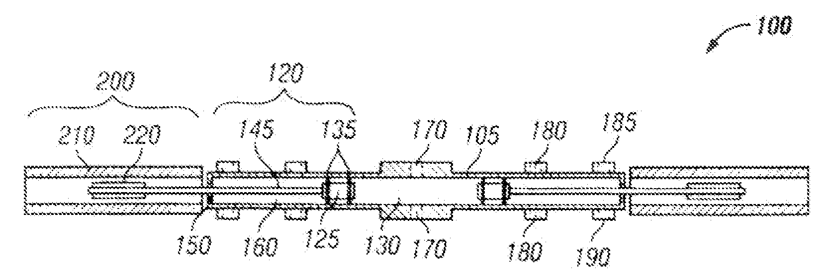
[0012]One embodiment of the invention is directed toward a linear combustion engine, comprising: a cylinder having a cylinder wall and a pair of ends, the cylinder including a combustion section disposed in a center portion of the cylinder; a pair of opposed piston assemblies adapted to move linearly within the cylinder, each piston assembly disposed on one side of the combustion section op...


PUM


Abstract

Various embodiments of the present invention are directed toward a linear combustion engine, comprising: a cylinder having a cylinder wall and a pair of ends, the cylinder including a combustion section disposed in a center portion of the cylinder; a pair of opposed piston assemblies adapted to move linearly within the cylinder, each piston assembly disposed on one side of the combustion section opposite the other piston assembly, each piston assembly including a spring rod and a piston comprising a solid front section adjacent the combustion section and a hollow back section comprising a gas spring that directly provides at least some compression work during a compression stroke of the engine; and a pair of linear electromagnetic machines adapted to directly convert kinetic energy of the piston assembly into electrical energy, and adapted to directly convert electrical energy into kinetic energy of the piston assembly for providing compression work during the compression stroke; wherein the engine includes a variable expansion ratio greater than 50:1.

Description

REFERENCE TO RELATED APPLICATIONS[0001]This application is a continuation-in-part of U.S. patent application Ser. Nos. 12 / 953,277 and 12 / 953,270 filed Nov. 23, 2010, the contents of which are incorporated herein by reference in their entireties.FIELD OF THE INVENTION[0002]The present invention relates to high-efficiency linear combustion engines and, more particularly, some embodiments relate to high-efficiency linear combustion engines capable of reaching high compression / expansion ratios by utilizing a free-piston engine architecture in conjunction with a linear electromagnetic machine for work extraction and an innovative combustion control strategy.DESCRIPTION OF THE RELATED ART[0003]Engine power density and emission have improved over the past 30 years; however overall efficiency has remained relatively constant. It is well known in the engine community that increasing the geometric compression ratio of an engine increases the engine's theoretical efficiency limit. Additionally...

Claims


Application Information

Patent Timeline
IPC IPC(8): F02B23/00F02B9/02F02B75/02F02B71/04
CPCF01B11/002F02B71/04F02B63/041
Inventor SIMPSON, ADAMMILLER, SHANNONSVRCEK, MARK
Owner MAINSPRING ENERGY INC
Why Eureka
Try Eureka