
Gas spring assembly and method

a technology of gas springs and springs, which is applied in the direction of shock absorbers, manufacturing tools, transportation and packaging, etc., can solve the problems of not being known or believed to be used, the known clip rings are not suitable for providing sufficient support, and the construction is poorly suited to applications, etc., to achieve the effect of low manufacturing cost and easy assembly

Active Publication Date: 2008-10-09
FIRESTONE IND PROD COMPANY
View PDF9 Cites 41 Cited by
  • Summary
  • Abstract
  • Description
  • Claims
  • Application Information

AI Technical Summary

Benefits of technology

[0007]It is desirable to develop a simplified gas spring construction that overcomes the foregoing problems and difficulties while maintaining a relatively low cost of manufacture and ease of assembly.

Problems solved by technology

It will be recognized, however, that such constructions are poorly suited for applications in which the gas spring assembly will be stretched or otherwise placed in tension, as this could generate an undesirable separation between the flexible wall and the piston of the gas spring assembly.
Typically, however, known clip rings are not suitable for providing sufficient support to withstand a tension load being applied to the gas spring assembly without an undesirable separation between the flexible wall and the piston.
Accordingly, such constructions are not known or believed to be used in applications in which tension loads occur.

Method used


Image

  • Gas spring assembly and method
  • Gas spring assembly and method
  • Gas spring assembly and method

Examples


Embodiment Construction

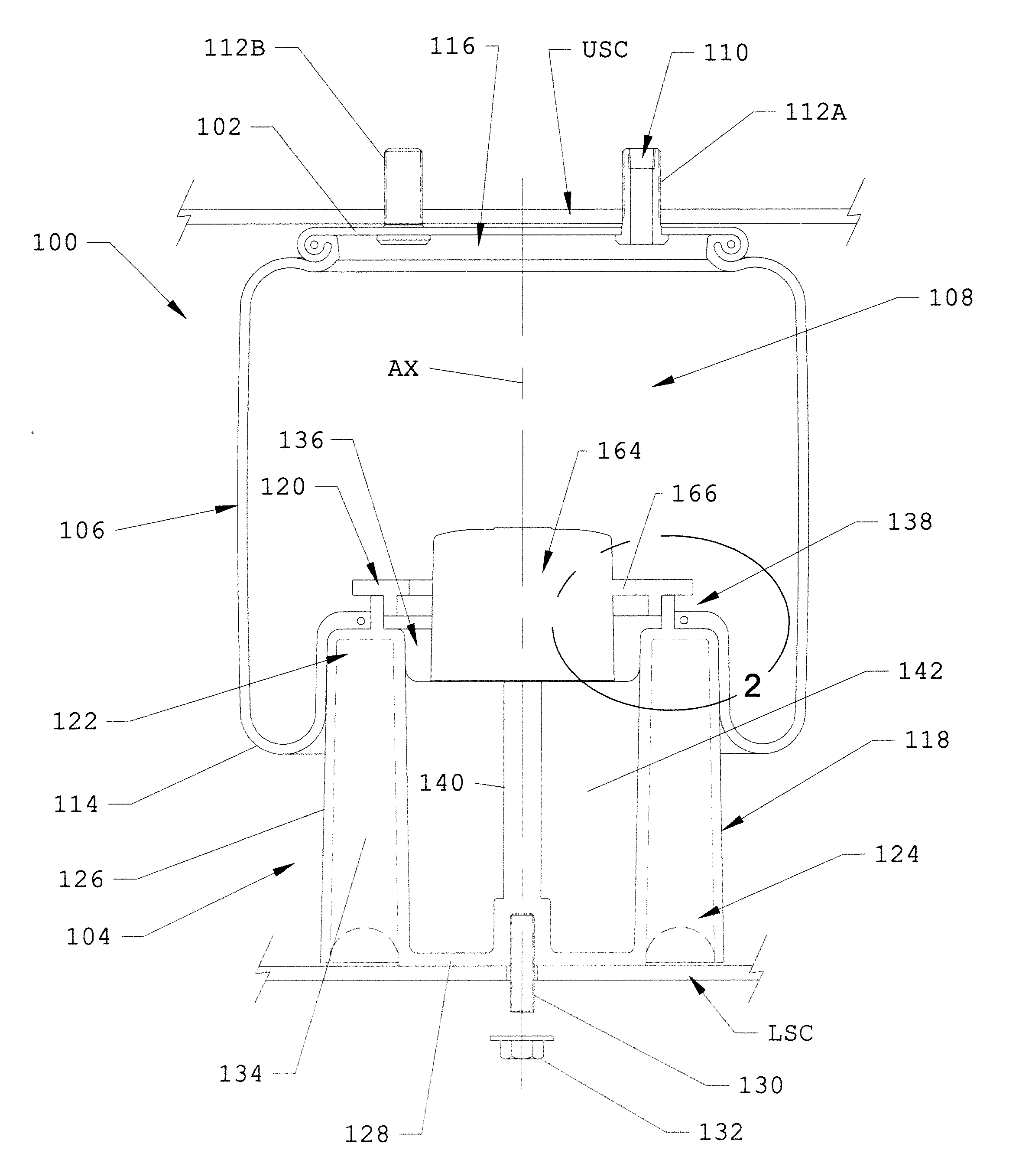
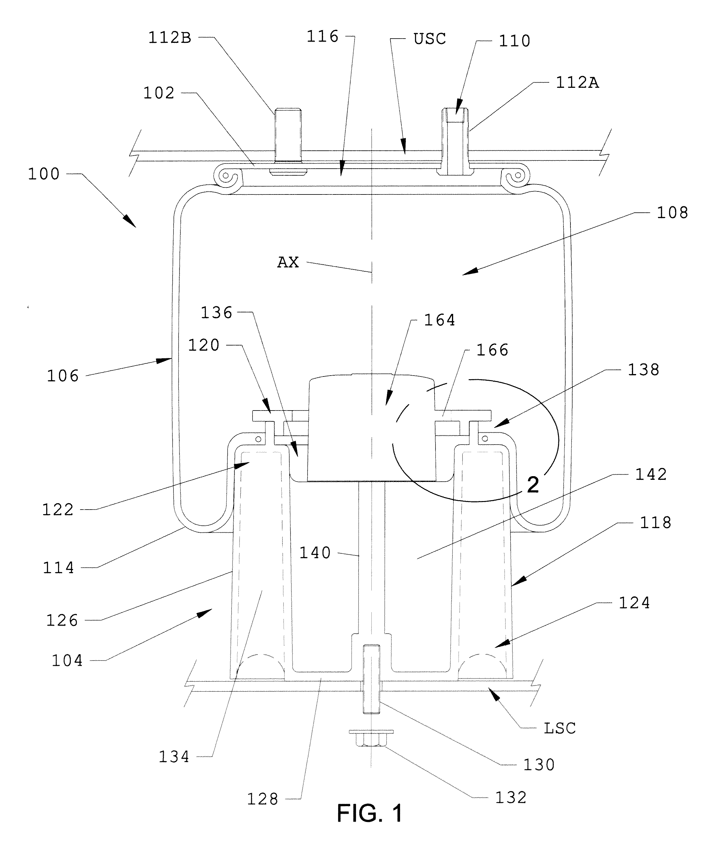
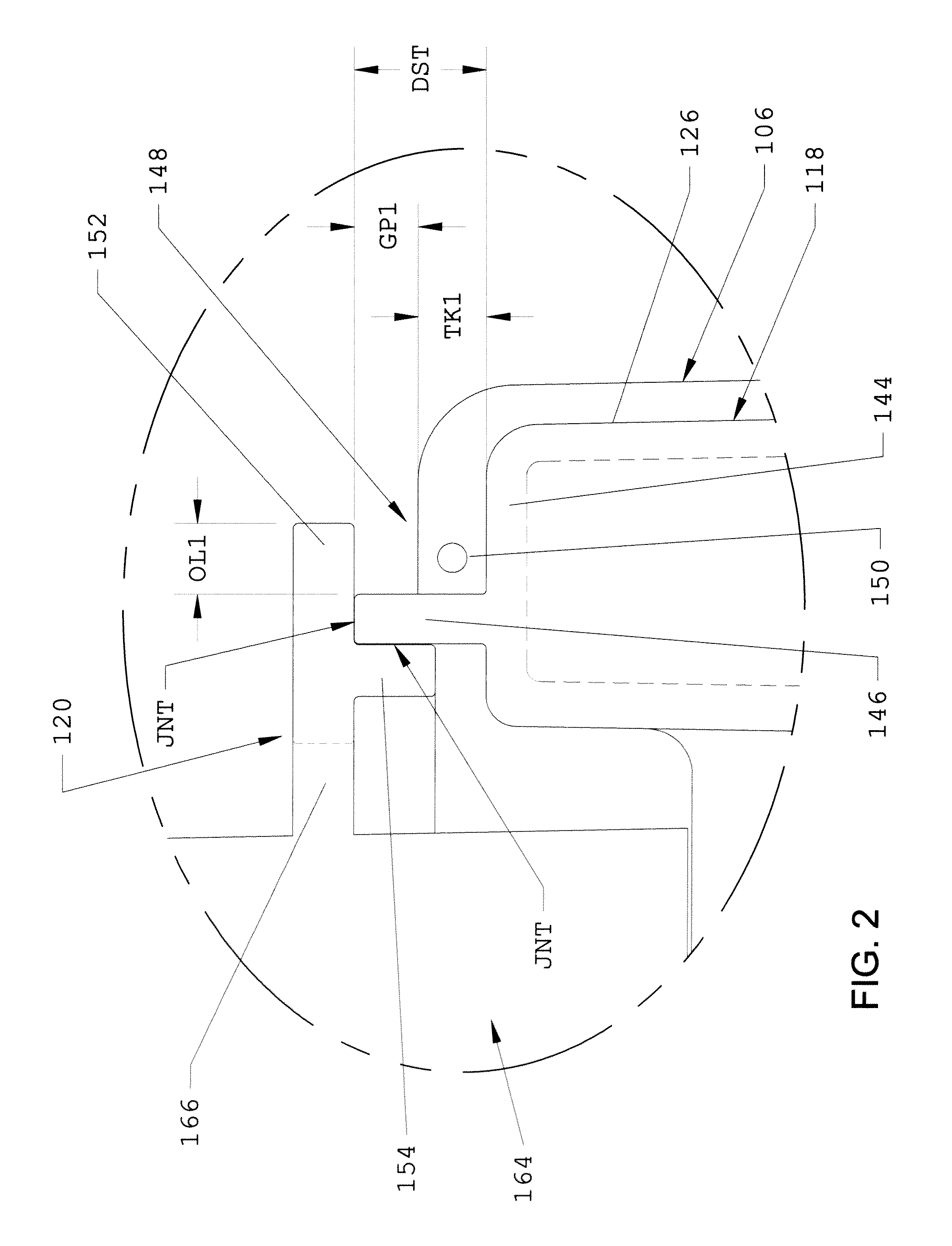
[0014]Turning now to the drawings wherein the showings are for the purpose of illustrating exemplary embodiments of the subject matter of the present disclosure and not for the purpose of limiting the same, FIG. 1 illustrates a gas spring assembly 100 that includes a first or upper end member 102 and a piston assembly 104 spaced from the first end member. A flexible wall 106 is secured between the first end member and the piston assembly and at least partially defines a spring chamber 108 therebetween. Preferably, the gas spring assembly contains a quantity of pressurized gas that can be transferred into and out of spring chamber 108 in any suitable manner, such as, for example, through a suitable gas transmission line (not shown) connected to a passage 110 extending through a mounting stud 112A. Additionally, the gas spring assembly can be installed or otherwise used in any suitable application or environment, such as use in a vehicle suspension system or an industrial mounting app...


PUM

PropertyMeasurementUnit
flexibleaaaaaaaaaa
thicknessaaaaaaaaaa
dimensionaaaaaaaaaa

Abstract

A gas spring assembly includes a first end member, a piston assembly and a flexible wall extending therebetween. The piston assembly includes a piston body receiving a portion of the flexible wall and a retainment ring for retaining the flexible wall on the piston body. A method of assembly is also included.

Description

[0001]This application claims priority from U.S. Provisional Application Ser. No. 60 / 922,452 filed on Apr. 9, 2007, which is hereby incorporated herein by reference in its entirety.BACKGROUND[0002]The subject matter of the present disclosure broadly relates to the art of vehicle suspension systems and, more particularly, to a gas spring assembly that includes a two-piece piston assembly capable of retaining a flexible wall thereon while the gas spring assembly is undergoing a tension load. The subject matter of the present disclosure also relates to a method of assembling such a gas spring assembly.[0003]Wheeled motor vehicles of most types and kinds include a sprung mass, such as a body or chassis, for example, and an unsprung mass, such as two or more axles or other wheel-engaging members, for example, with a suspension system disposed therebetween. Typically, a suspension system will include a plurality of spring devices as well as a plurality of damping devices that together per...

Claims


Application Information

Patent Timeline
Patent Type & Authority Applications(United States)
IPC IPC(8): B23P19/04F16F9/04F16F5/00F16F9/00
CPCB60G11/28Y10T29/53613B60G2204/126B60G2204/44B60G2204/4502B60G2206/424B60G2206/71B60G2206/7101B60G2206/8101B60G2206/81012B60G2206/8201B60G2206/82013B60G2206/8209B60G2206/82092B60G2206/821F16F9/0454F16F9/057B60G2202/152
Inventor LEVY, DANIEL I.HALL, JONATHAN
Owner FIRESTONE IND PROD COMPANY
Learn More