
Manufacturing method for metal mark plate

a manufacturing method and metal mark technology, applied in metal working equipment, manufacturing tools, welding apparatus, etc., can solve the problems of difficult control and monitoring the yield rate, inability to use precise mass production, complex and time-consuming current methods, etc., to achieve fast and stable welding technique, improve production efficiency, and simplify manufacturing procedures

Inactive Publication Date: 2012-06-07
CHENMING MOLD IND CORP
View PDF1 Cites 0 Cited by
  • Summary
  • Abstract
  • Description
  • Claims
  • Application Information

AI Technical Summary

Benefits of technology

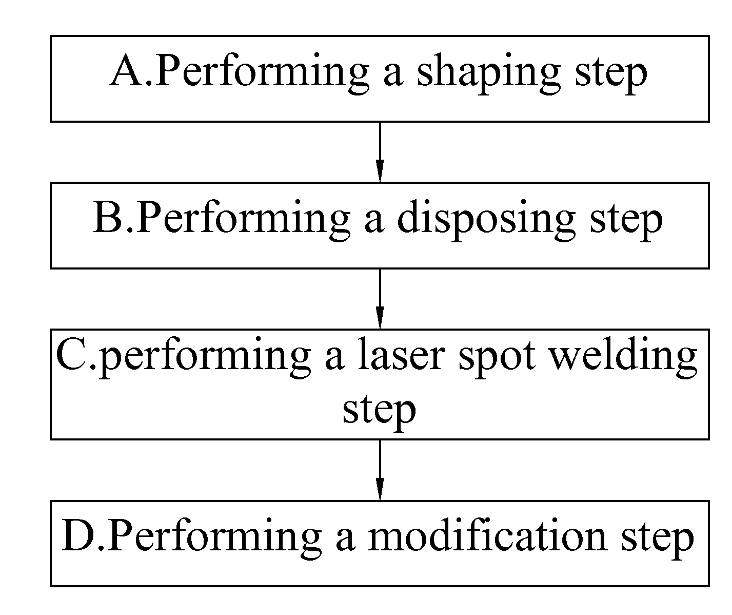
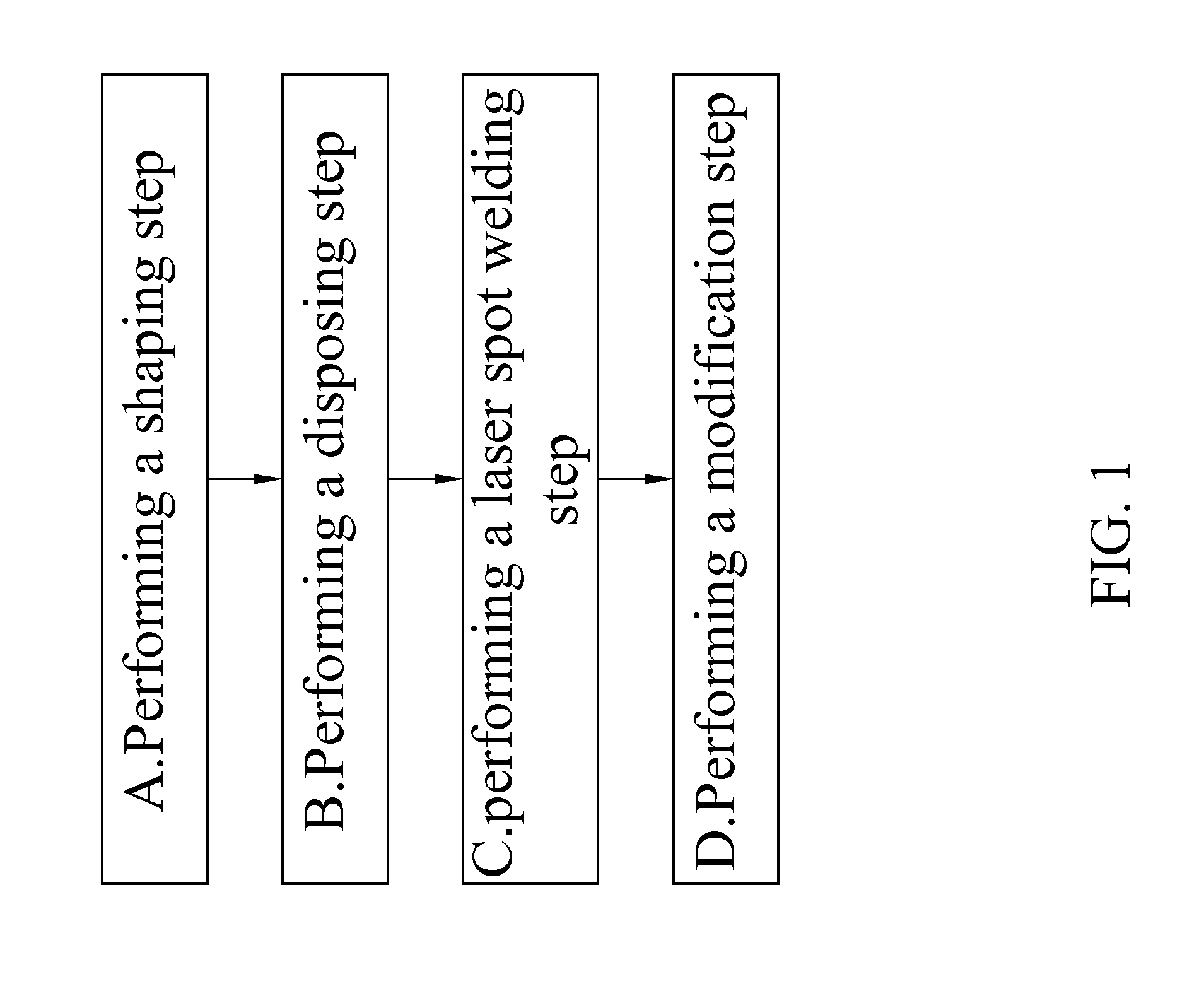
[0010]Step C: performing a laser spot welding step by contacting the connection surface of the metal mark part to the region of the metal base plate on which the welding flux layer is disposed, and then heating a backside of the region of the metal base plate on which the welding flux layer is disposed by a laser for fixedly fixing the metal mark part, the welding flux layer, and the metal base plate with one another so as to provide with a high bonding strength therebetween.
[0011]The manufacturing method for a metal mark plate of the present invention further comprises a Step D: performing a modification step to the appearance of the assembled metal mark part and metal base plate, wherein the modification step is performed by a surface polishing method or a hairline-electroplating method in order to increase the quality of the surface thereof.
[0016]The manufacturing method for a metal mark plate of the present invention is designed to firstly dispose the welding flux layer on the metal base plate and arrange the metal mark part on the region of the metal base plate on which the welding flux layer is disposed, then perform the laser spot welding step to assemble the metal mark part with the metal base plate by heating the backside of the metal base plate at a location corresponding to the welding flux layer. The present invention therefore provides a fast and stable welding technique for manufacturing a metal mark plate. Since the manufacturing procedure is simplified, the present invention can be applied to automatic production and precise mass production could thereby be accomplished.

Problems solved by technology

However, the current methods are mostly complex and time- consuming and labor-consuming, and it is also a difficulty to control and monitor the yield rate thereof Furthermore, the current methods do not comply with the requirement of automatic productions and can not be used for precise mass production.

Method used


Image

  • Manufacturing method for metal mark plate
  • Manufacturing method for metal mark plate
  • Manufacturing method for metal mark plate

Examples


Embodiment Construction

[0024]The above and further objects and novel features of the invention will more fully appear from the following detailed description when the same is read in connection with the accompanying drawing. It is to be expressly understood, however, that the drawing is for purpose of illustration only and is not intended as a definition of the limits of the invention.

[0025]Please refer to FIG. 1 for a preferred embodiment of the manufacturing method for a metal mark plate according to the present invention that comprises:

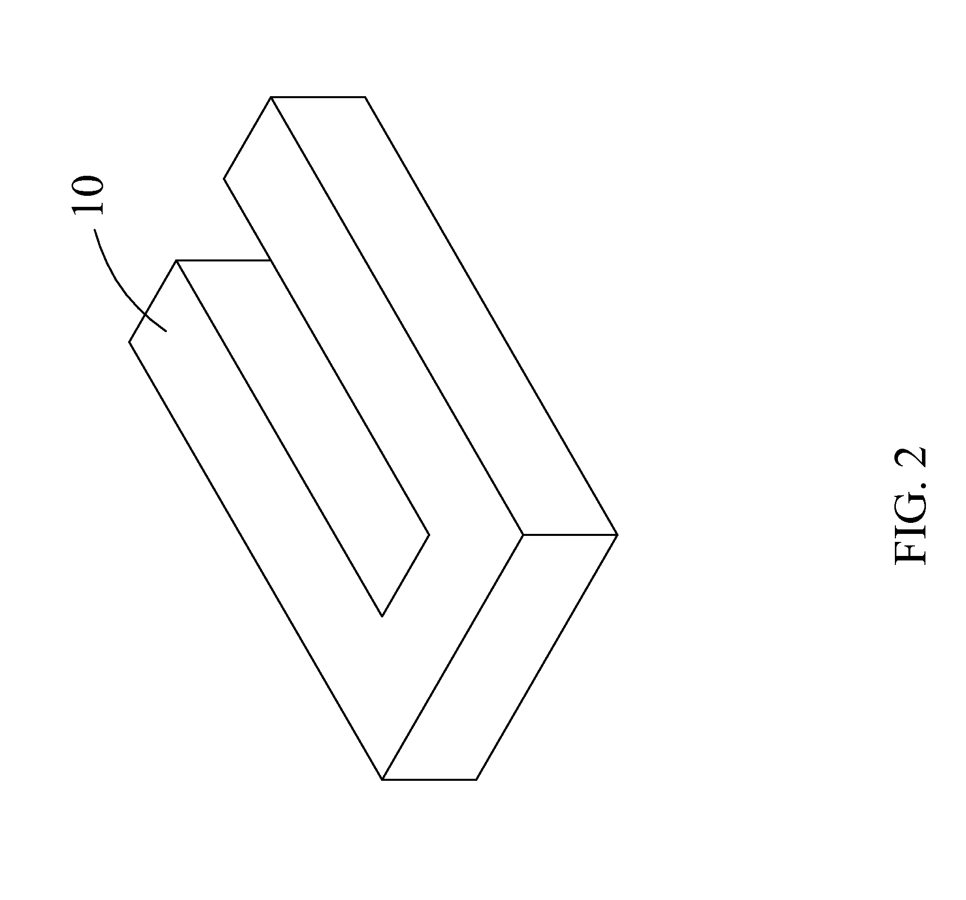
[0026]Step A: performing a shaping step by shaping a metal material into several metal mark parts by a one-shot forming technique, wherein a bottom surface of each of the metal mark parts is a connection surface;

[0027]Step B: performing a disposing step by disposing a welding flux layer onto at least one region of a surface of the metal base plate;

[0028]Step C: performing a laser spot welding step by contacting the connection surface of at least one of the metal mark par...


PUM

PropertyMeasurementUnit
bonding strengthaaaaaaaaaa
shapeaaaaaaaaaa
thicknessaaaaaaaaaa

Abstract

A manufacturing method for a metal mark plates is disclosed. In this manufacturing method, a welding flux layer is firstly disposed onto a metal base plate, and a plurality of metal mark parts are arranged on corresponding regions of the metal base plate on which the welding flux layer is disposed. Thereafter, a laser spot welding step is performed to assemble the metal mark parts with the metal base plate by heating the backside of the metal back plate at a location corresponding to the welding flux layer. This manufacturing method therefore provides a fast and stable welding way for manufacturing the metal mark plate. Besides, this manufacturing method can be applied for automatic production and precise mass production could thereby be accomplished.

Description

BACKGROUND OF THE INVENTION[0001]1. Field of the Invention[0002]The present invention relates to a manufacturing method for a metal mark plate, and more particularly, to a method for manufacturing a metal mark plate in fast speed and high quality.[0003]2. Brief Description of the Related Art[0004]Metal mark plates are often disposed on a product or an object as marks or logos of a brand or a trademark. Several specific characters or specific patterns are protruded from the metal mark plates to provide with a three-dimensional appearance for thereby providing a stronger impression on the viewer.[0005]The existing metal mark plate is manufactured by various kinds of methods. For example, a metal character or pattern is formed by a cutting method, and then the metal character or pattern is fixedly adhered or riveted to a metal base plate. However, the current methods are mostly complex and time- consuming and labor-consuming, and it is also a difficulty to control and monitor the yield...

Claims


Application Information

Patent Timeline
Patent Type & Authority Applications(United States)
IPC IPC(8): B23K26/00
CPCB23K26/203Y10T29/4998B23K26/22B23K26/211
Inventor CHAO, YU-TOCHANG, HSUEH-TSUCHIOU, YAU-HUNG
Owner CHENMING MOLD IND CORP
Learn More