Micro switch

Inactive Publication Date: 2012-06-07
WELL SHIN TECH
View PDF5 Cites 8 Cited by
  • Summary
  • Abstract
  • Description
  • Claims
  • Application Information

AI Technical Summary

Benefits of technology

[0005]A primary object of the present invention is to provide a micro switch having simple structures including a pu

Problems solved by technology

However, the structure of the traditional micro switch 100′ is

Method used


Image

  • Micro switch
  • Micro switch
  • Micro switch

Examples


Embodiment Construction

[0027]The structure and the technical means adopted by the present invention to achieve the above and other objects can be best understood by referring to the following detailed description of the preferred embodiments and the accompanying drawings. Furthermore, directional terms described by the present invention, such as upper, lower, front, back, left, right, inner, outer, side and etc., are only directions by referring to the accompanying drawings, and thus the used directional terms are used to describe and understand the present invention, but the present invention is not limited thereto.

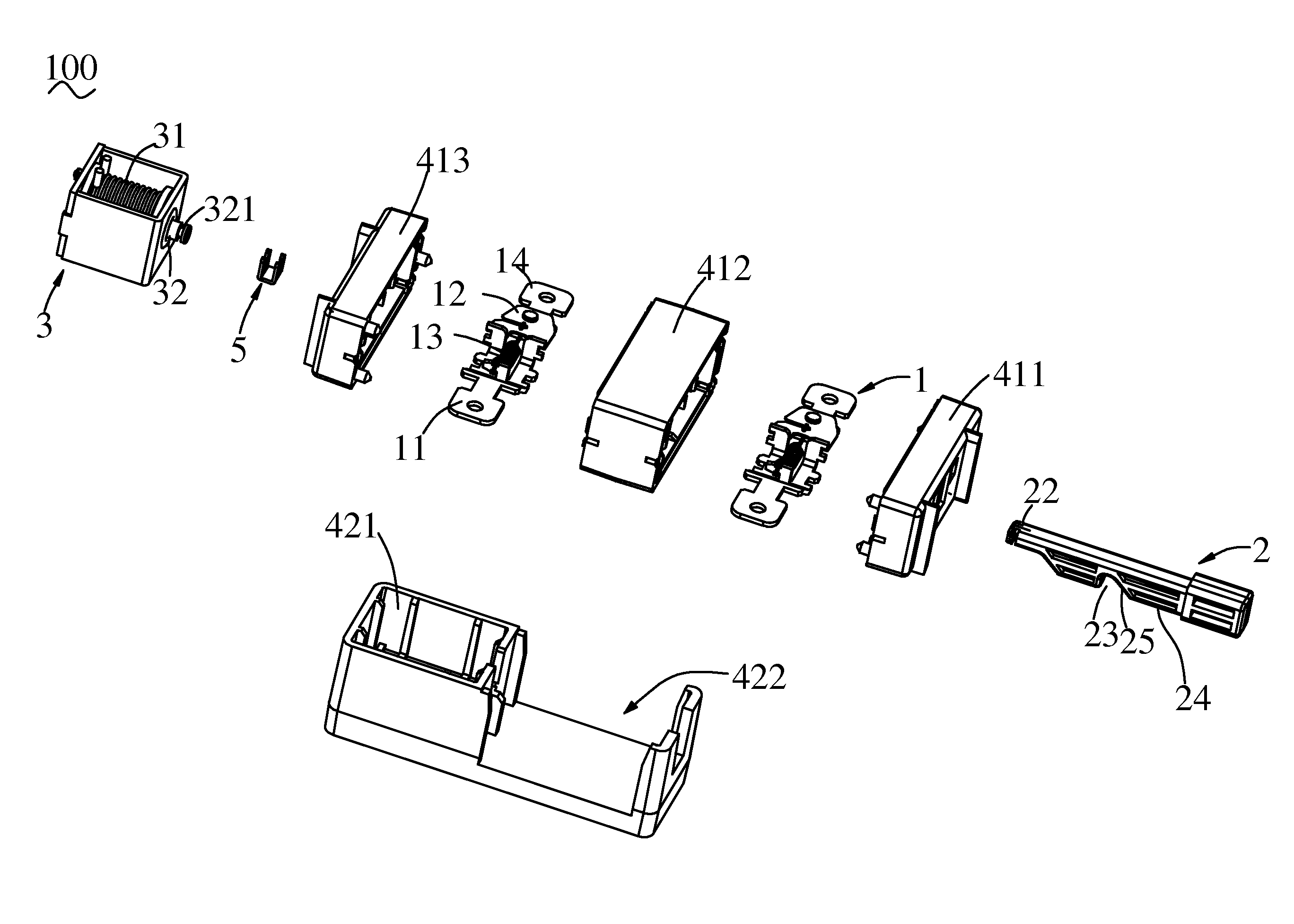
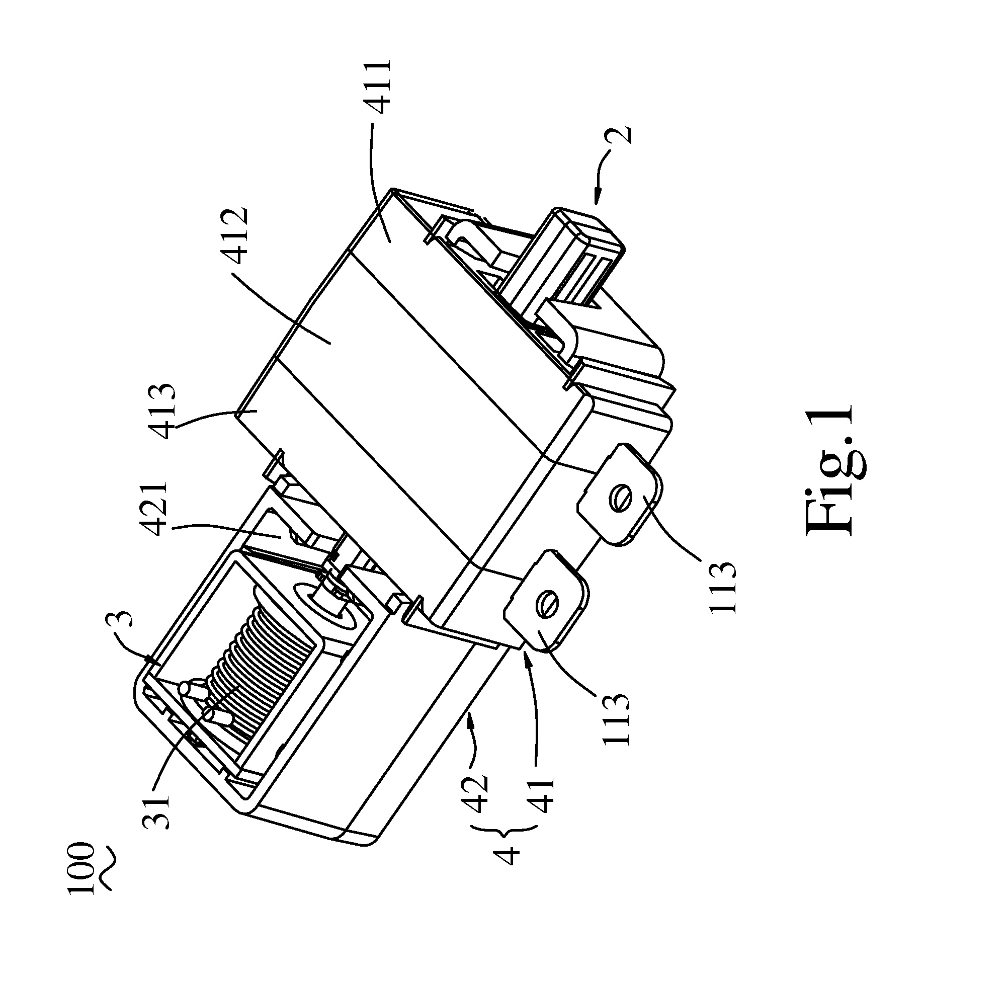
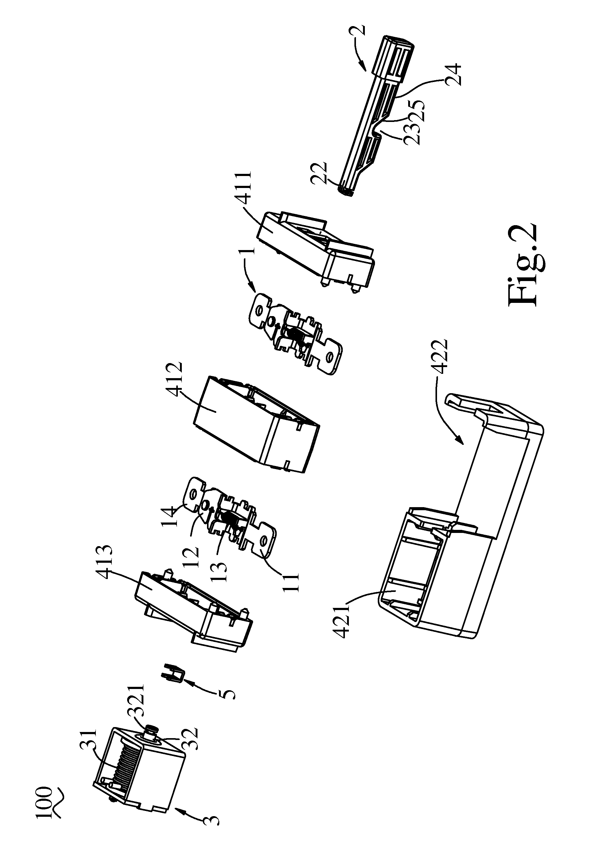
[0028]Referring now to FIGS. 1 and 2, a micro switch according to a preferred embodiment of the present invention is illustrated. As shown, a micro switch 100 comprises two conductive terminal assemblies 1, a push rod 2 and an electro-magnet 3 and a bracket 4.

[0029]Referring now to FIGS. 2, 3 and 4, each of the two conductive terminal assemblies 1 comprises a first terminal 11, an elastically ...


PUM


Abstract

A micro switch is disclosed and includes a bracket, at least one conductive terminal assembly, a push rod and an electro-magnet. The conductive terminal assembly has a first terminal, an elastically conductive plate, a spring and a second terminal. A first end of the spring is hooked on the first terminal, and a second end thereof is hooked on the elastically conductive plate. The push rod is slidably installed on the bracket, and has a recess, a sliding inclined surface and a top flat surface. The push rod can be slid to cause the spring to slide into the recess and onto the top flat surface. Thus, the spring can actuate the elastically conductive plate to pivotally rotate and abut against the second terminal. Thus, the structure of the micro switch is simplified and the installation thereof is easier.

Description

FIELD OF THE INVENTION[0001]The present invention relates to a micro switch, and more particularly to a micro switch having simple structures including a push rod used to directly control switch operations.BACKGROUND OF THE INVENTION[0002]Referring now to FIGS. 10, 11 and 12, a traditional micro switch 100′ is illustrated. As shown, the traditional micro switch 100′ comprises a coil 1′, an armature 2′, a release spring 3′, a return button 4′, a return spring 5′, a brake plate 6′, a balance frame 7′, a contact switch 8′ and a pull rod 9′, wherein the pull rod 9′ is a metal cylinder combined with the return button 4′ by hot casting. A lower end of the pull rod 9′ has a flange 91′ which has an upper surface 911′ and a lower surface 912′. The brake plate 6′ has a first lock hole 61′ and a second lock hole 62′, wherein the first lock hole 61′ has a right vertical surface 611′ and a left curved surface 612′. The balance frame 7′ has a first opening 71′ and a second opening 72′ formed alon...

Claims


Application Information

Patent Timeline
IPC IPC(8): H01H3/02
CPCH01H50/14H01H50/647H01H50/641
Inventor WU, JUI-HSIUNG
Owner WELL SHIN TECH
Why Eureka
Try Eureka