Laminated battery structure, secondary battery pack comprising same and battery pack module

A laminated, battery pack technology, applied in secondary batteries, circuits, electrical components, etc., can solve the problems of unguaranteed battery safety, poor battery cycle performance, a lot of time and energy, etc., to improve production and preparation. Efficiency, the effect of improving production and preparation efficiency, and reducing production and manufacturing costs

Inactive Publication Date: 2016-11-16
HIGHPOWER TECH HUIZHOU
View PDF6 Cites 17 Cited by
  • Summary
  • Abstract
  • Description
  • Claims
  • Application Information

AI Technical Summary

Problems solved by technology

The deformation of the battery structure leads to uneven gaps between the electrodes, the cycle performance of the battery will deteriorate sharply, and the safety of the battery cannot be guaranteed due to the short circuit inside the battery
Second, manufacturing a stacked battery structure by sequentially stacking multiple unit negative electrodes and multiple unit positive electrodes requires a lot of time and effort to perform the sequential stacking process, resulting in low productivity in this process

Method used


Image

  • Laminated battery structure, secondary battery pack comprising same and battery pack module
  • Laminated battery structure, secondary battery pack comprising same and battery pack module
  • Laminated battery structure, secondary battery pack comprising same and battery pack module

Examples


Embodiment 1

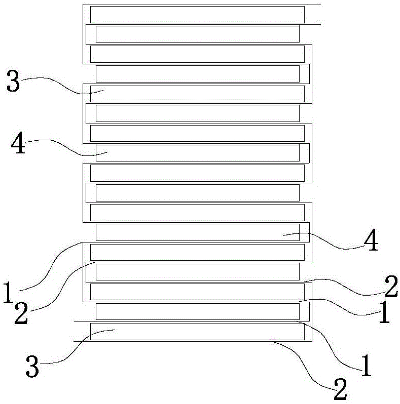
[0028] refer to figure 1 , figure 1 It is the structural diagram of the stacked battery in Example 1. The present invention provides a stacked battery structure, including a battery cell, and the battery cell includes two layers of continuous separators 1, 2 oppositely arranged, and the two layers are continuous A plurality of first battery cells 3 arranged at intervals are sandwiched between the continuous separators 1, 2, and the two layers of continuous separators 1, 2 and the first battery cells 3 sandwiched between them are folded in a zigzag to form a stack. A sheet battery cell, the second battery unit 4 is sandwiched between the outer sides of the two continuous separators 1 and 2, and the two pole pieces of the second battery unit 4 and the first battery unit 3 are close to each other to form an electrode pair. In this embodiment, the first battery unit 3 is a negative unipolar sheet, the second battery unit 4 is a positive unipolar sheet, and the outermost electrod...

Embodiment 2

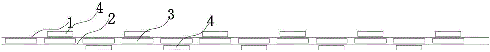
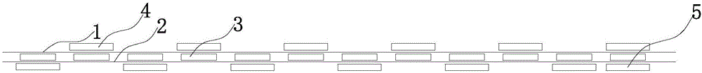
[0032] refer to Figure 3-4 , image 3 It is the structure diagram before the battery structure of Example 2 is folded, Figure 4 It is the structural diagram of the laminated battery of Embodiment 2. This embodiment is basically the same as Embodiment 1, the difference is that: the first battery unit 3 is a positive monopolar sheet, and the second battery unit 4 is a negative monopolar sheet. pole piece. After folding, the outermost pole piece of the laminated battery structure is a negative pole piece, that is, a negative pole piece is arranged below the first and last first battery unit 3 or the outer pole piece is a negative pole structure , in this embodiment, a negative electrode sheet 5 is arranged below the first and the last first battery unit 3 respectively.

Embodiment 3

[0034] refer to Figure 5 , Figure 5 It is the structural diagram of the battery structure of Example 3 before folding. This embodiment is basically the same as that of Example 1, except that the first battery unit 3 is a positive electrode / diaphragm / negative electrode structure, and the even-numbered cells from the second one are The second battery unit 4 corresponding to the first battery unit 3 is arranged on the upper continuous separator 1, and the second battery unit 4 corresponding to the odd-numbered first battery unit 3 from the third is arranged on the Below the continuous diaphragm 2 of the lower layer, the second battery unit 4 arranged on the continuous diaphragm 1 of the upper layer is a structure in which the negative electrode single pole piece or the outer pole pieces are all negative electrodes, and the continuous diaphragm 1 of the lower layer is arranged The second battery unit 4 below is a structure in which the positive pole piece or the outer pole piec...


PUM


Abstract

The invention discloses a laminated battery structure, a secondary battery pack comprising the same and a battery pack module. The laminated battery structure comprises a battery cell, wherein the battery cell comprises two layers of continuous diaphragms which are oppositely arranged; a plurality of first battery units arranged at intervals are clamped between the two layers of continuous diaphragms; the two layers of continuous diaphragms and the first battery units clamped between the continuous diaphragms are folded in a zigzag form to form the laminated battery cell; second battery units are clamped between the outer sides of the continuous diaphragms; and two pole pieces, which are close to each other, of each second battery unit and the corresponding first battery unit form one electrode pair. By the structure with the two layers of continuous diaphragms, on one hand, the stability of the battery structure is higher and the cycle performance of batteries is improved; and on the other hand, the production and preparation efficiency of the batteries can be improved.

Description

technical field [0001] The invention relates to the field of batteries, in particular to a laminated battery structure, a secondary battery pack and a battery pack module including the same. Background technique [0002] In today's society, with the rapid development of mobile devices and increasing demand, coupled with the vigorous promotion of new energy vehicles, the battery industry, which is the energy source of mobile devices, is booming. Therefore, a lot of investigation and research have been done on various market demands. The requirements for battery volumetric energy density and gravimetric energy density are getting higher and higher, and there is a high demand for lithium-ion polymer batteries and battery packs with high performance, high stability, and high safety. With the vigorous development of new energy vehicles, power lithium-ion batteries are facing great challenges in reducing manufacturing costs. Therefore, the structure of the battery assembly can b...

Claims


Application Information

Patent Timeline
Patent Type & Authority Applications(China)
IPC IPC(8): H01M10/0583
CPCH01M10/0583Y02E60/10Y02P70/50
Inventor 程君刘灿李文良李小兵陈永爱马丽萍
Owner HIGHPOWER TECH HUIZHOU
Why Eureka
Try Eureka