Controls for paper, sheet, and box manufacturing systems

a technology of control system and paper, applied in the field of preprint paper, sheet and box manufacturing system, can solve the problems of waste of time and product, each sheet or box structure on the corrugated board web still needs to be cut, etc., to avoid significant product waste, improve manufacturing efficiency, and improve image quality and variability

Active Publication Date: 2019-01-17
GEORGIA PACIFIC CORRUGATED
View PDF11 Cites 15 Cited by
  • Summary
  • Abstract
  • Description
  • Claims
  • Application Information

AI Technical Summary

Benefits of technology

[0005]Embodiments of the present invention provide systems for providing efficient manufacturing of sheet or box structures for corrugate. However, some embodiments of the present invention are contemplated for extension into other product manufacturing, including other paper based product manufacturing, such as folded carton, beverage, labels, flexible paper, industrial bags, plates, cups, décor, and many others.
[0006]Using digital print processes, enhanced image quality and variability can be achieved for images on the corrugated sheet or box (or other products). In particular, the digital printing may occur prior to formation of the layered corrugate (“pre-print”) to avoid printing difficulties and reliability for printing on the multi-layered corrugated structure.
[0007]In order to increase efficiency of manufacturing, some embodiments of the present invention contemplate various methods for control of the corrugator, enabling avoidance of significant product waste. To explain, one difficulty of printing during the pre-print phase is that each sheet or box structure on the corrugated board web still needs to be cut. However, it is important for the cut to be accurate since the printed images are already on the corrugated board web (e.g., you don't want to cut through an image or have an off center image for the sheet or box structure). In some embodiments, one or more corrugator plans and / or associated reel maps may be used to determine where to position and / or perform cuts with various knives of the corrugator for each sheet or box structure. However, manual checking of a corrugator plan and / or associated reel map and / or adjustment of the corrugator (such as the placement of the knives, slitters, or scorers) wastes time and product (e.g., when the corrugator is still running). In this regard, the present invention contemplates using various methods to achieve simplified automated control of the corrugator.
[0008]For example, in some embodiments, one or more colored markings may be used to indicate an order change section between two order sections. The colored markings may be detected as the corrugator runs and once detected, a controller may determine a next set of order instructions—e.g., changing order instructions to match the upcoming order. In such a regard, an order change may occur, thereby enabling automated control of the corrugator based on the new order instructions in order to cut new sheet or box structures during the upcoming order section. In some embodiments, the colored markings may be in the form of a standard cut-to-mark marking, but with a distinguishable color. In such a regard, the colored cut-to-mark marking may enable both detection of the order change section and cause initiation of one or more cuts to the corrugated board web. Another benefit of the proposed colored markings is the simplicity of the solution to enable a “blind” order change without requiring checking of the corrugator plan. This enables quick, easy and automated changing of the order instructions without utilizing computer “readable” markings.

Problems solved by technology

To explain, one difficulty of printing during the pre-print phase is that each sheet or box structure on the corrugated board web still needs to be cut.
However, manual checking of a corrugator plan and / or associated reel map and / or adjustment of the corrugator (such as the placement of the knives, slitters, or scorers) wastes time and product (e.g., when the corrugator is still running).

Method used


Image

  • Controls for paper, sheet, and box manufacturing systems
  • Controls for paper, sheet, and box manufacturing systems
  • Controls for paper, sheet, and box manufacturing systems

Examples


Embodiment Construction

[0049]Some example embodiments now will be described more fully hereinafter with reference to the accompanying drawings, in which some, but not all example embodiments are shown. Indeed, the examples described and pictured herein should not be construed as being limiting as to the scope, applicability or configuration of the present disclosure. Rather, these example embodiments are provided so that this disclosure will satisfy applicable legal requirements. Like reference numerals refer to like elements throughout.

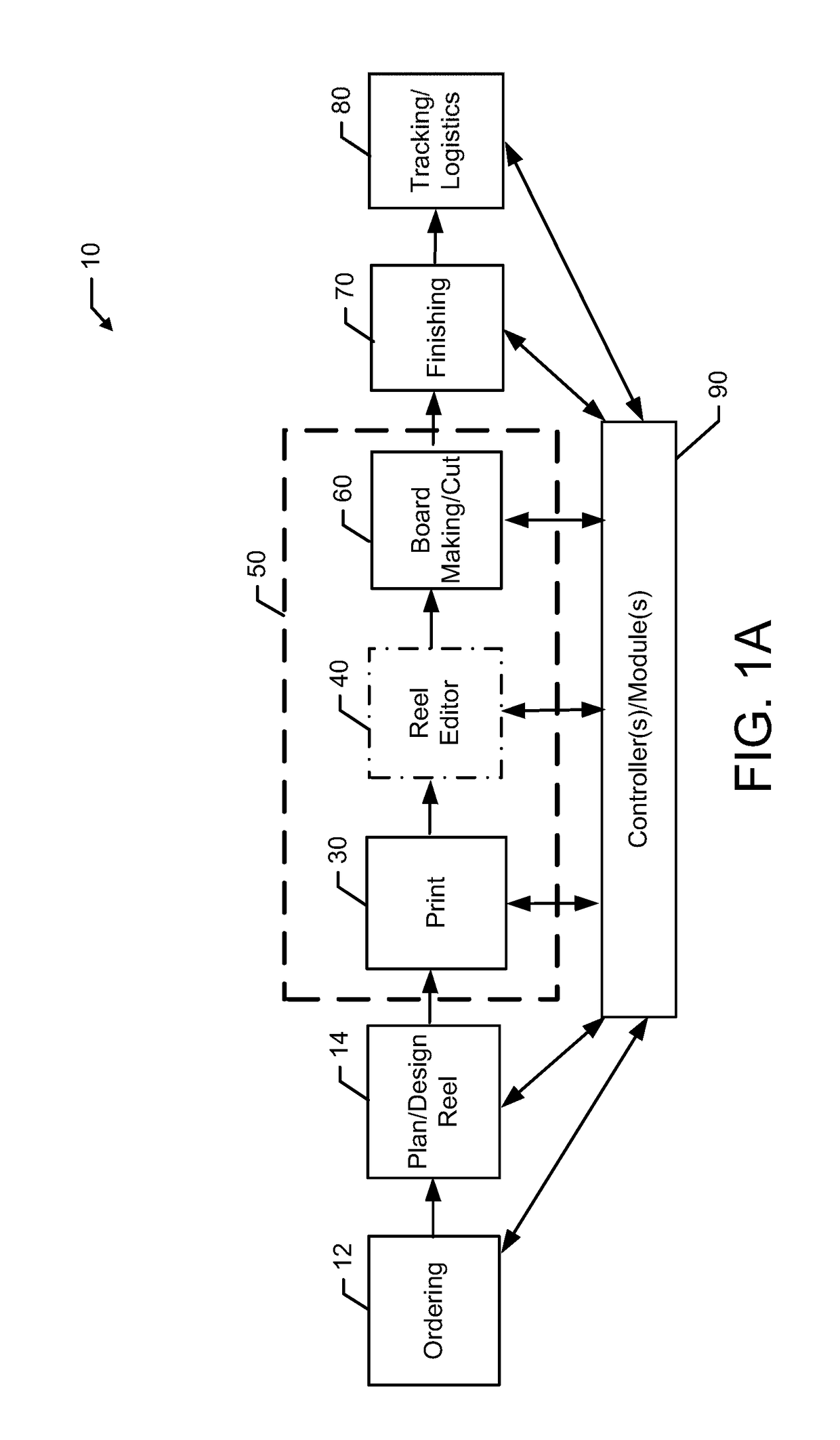
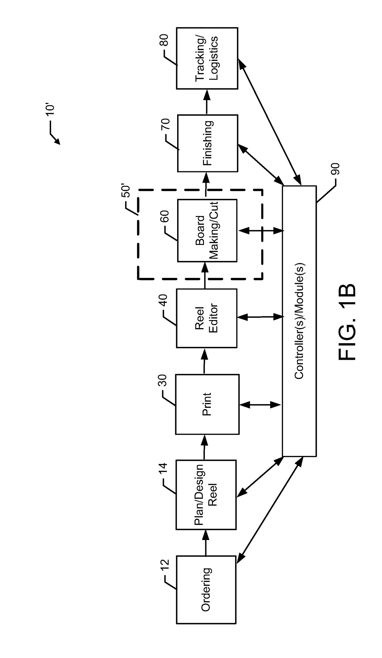
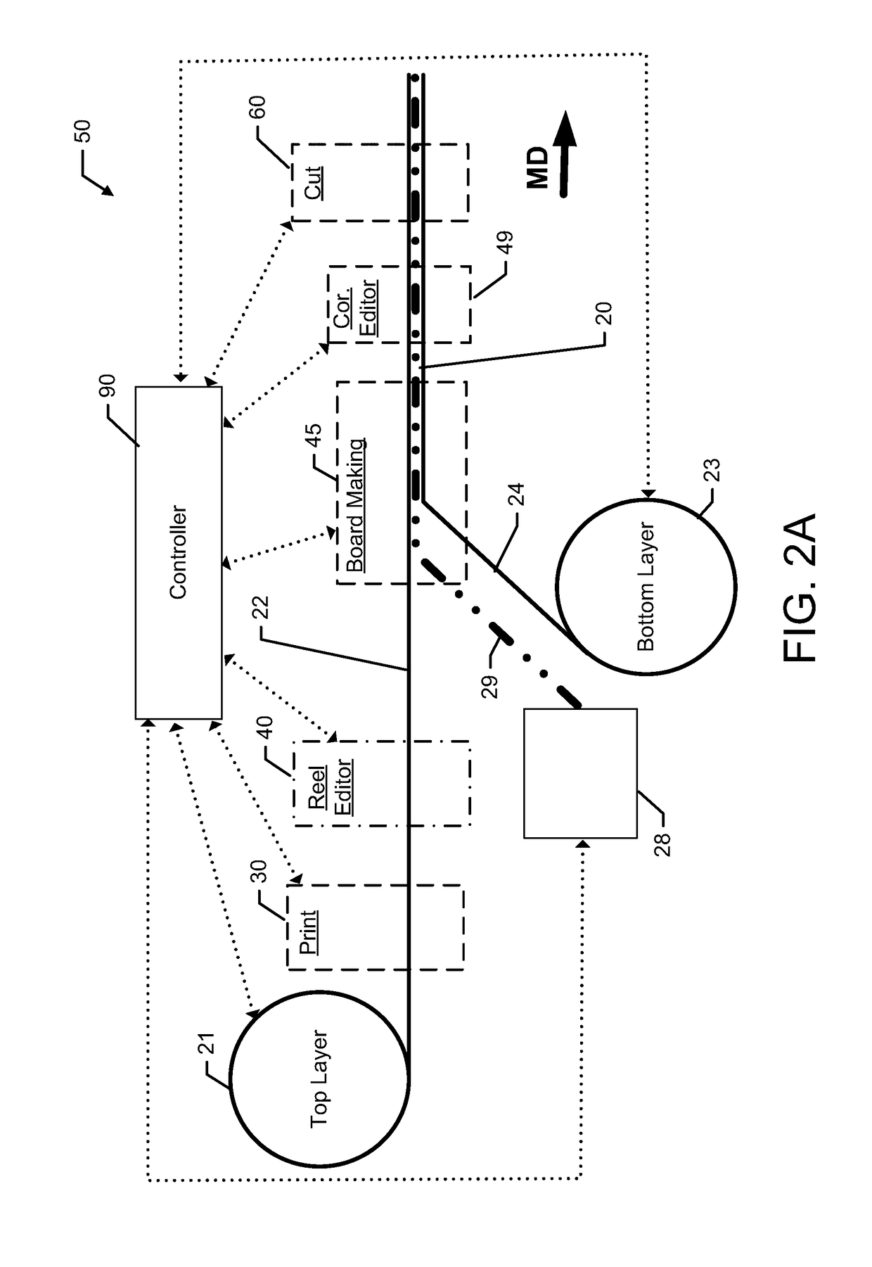
Example Corrugated Box Manufacturing Process

[0050]Corrugated sheet and box manufacturing is an example paper, sheet, and / or box manufacturing system. In some such manufacturing, a corrugator is used to glue together layers of board web with a flute medium positioned in between. Depending on the desired characteristics of the corrugate board web, different layers / arrangements can be combined. Once formed, the corrugate board web (e.g., top layer, flute medium, and bottom la...


PUM


Abstract

Systems for providing efficient manufacturing of sheet or box structures, corrugate sheets, or other products of varying size and structure often with pre-applied print (“pre-print”) are provided herein. The systems include various features and modules that enable automated control of the corrugator, including the knives, slitters, scorers and cut-to-mark detection system(s), are contemplated. Colored markings may be used to indicate an order change section between two order sections of a roll plan for the manufacturing process. The colored markings are detected as the corrugator runs and, once detected, a controller determines a next set of order instructions—e.g., to match the upcoming order. Thus, an order change may occur, thereby enabling automated control of the corrugator based on the new order instructions. Computer readable markings may enable checking of the actual position in the roll plan to an intended position, enabling stopping or changing of the corrugator operation if needed.

Description

CROSS REFERENCE TO RELATED APPLICATIONS[0001]This application claims priority to U.S. Provisional Patent Application No. 62 / 597,005, entitled “Controls for Paper, Sheet, and Box Manufacturing Systems”, filed Dec. 11, 2017; U.S. Provisional Patent Application No. 62 / 583,853, entitled “Controls for Paper, Sheet, and Box Manufacturing Systems”, filed Nov. 9, 2017; and U.S. Provisional Patent Application No. 62 / 532,483, entitled “Digital Pre-Print Paper, Sheet, and Box Manufacturing Systems”, filed Jul. 14, 2017, each of which is hereby incorporated by reference in its entirety.FIELD OF THE INVENTION[0002]Example embodiments of the present invention generally relate to paper, sheet and box manufacturing systems and, more particularly to, pre-print paper, sheet and box manufacturing systems.BACKGROUND[0003]Corrugated sheet and box manufacturing includes, in some cases, using a corrugator to glue together layers of board web with a flute medium positioned in between. Depending on the desi...

Claims


Application Information

Patent Timeline
Patent Type & Authority Applications(United States)
IPC IPC(8): B31B50/00B31B50/16B31B50/74B31F1/24
CPCB31B50/006B31F1/24B31B50/74B31B50/16B26D5/34B31F1/2822B31F1/2831B31B50/25B31B50/10B31B50/88B31B50/18B31F1/20B65H26/02B65H35/008B65H2551/00B65H2701/1762
Inventor WIDNER, ERNEST BARFIELDJAIN, AMITH SUBHASH CHANDRASEAY, ROBERT DENNIS
Owner GEORGIA PACIFIC CORRUGATED
Why Eureka
Try Eureka