Driving Method of Electrophoretic Display Device, Electrophoretic Display Device and Electronic Apparatus

a technology of display device and display device, which is applied in the direction of electric digital data processing, instruments, computing, etc., can solve the problems of display change according to environmental temperature, display which causes and may be visible, so as to achieve the effect of performing display without a sense of discomfor

Inactive Publication Date: 2012-06-07
SEIKO EPSON CORP
View PDF1 Cites 7 Cited by
  • Summary
  • Abstract
  • Description
  • Claims
  • Application Information

AI Technical Summary

Benefits of technology

[0020]According to the aspects of the invention, there are provided the driving method of an electrophoretic display device and the like which are capable of performing display without a sense of discomfort by suppressing

Problems solved by technology

However, in the electrophoretic display device, it is known that a display change occurs according to an environmental temperature.
As a result, even though a voltage, based on the same pulse signal as in a case where the environmental temperature is not the low

Method used


Image

  • Driving Method of Electrophoretic Display Device, Electrophoretic Display Device and Electronic Apparatus
  • Driving Method of Electrophoretic Display Device, Electrophoretic Display Device and Electronic Apparatus
  • Driving Method of Electrophoretic Display Device, Electrophoretic Display Device and Electronic Apparatus

Examples


first embodiment

1. First Embodiment

[0033]The first embodiment of the invention will be described with reference to FIG. 1 to FIG. 9B.

1.1. Electrophoretic Display Device

1.1.1. Configuration of Electrophoretic Display Device

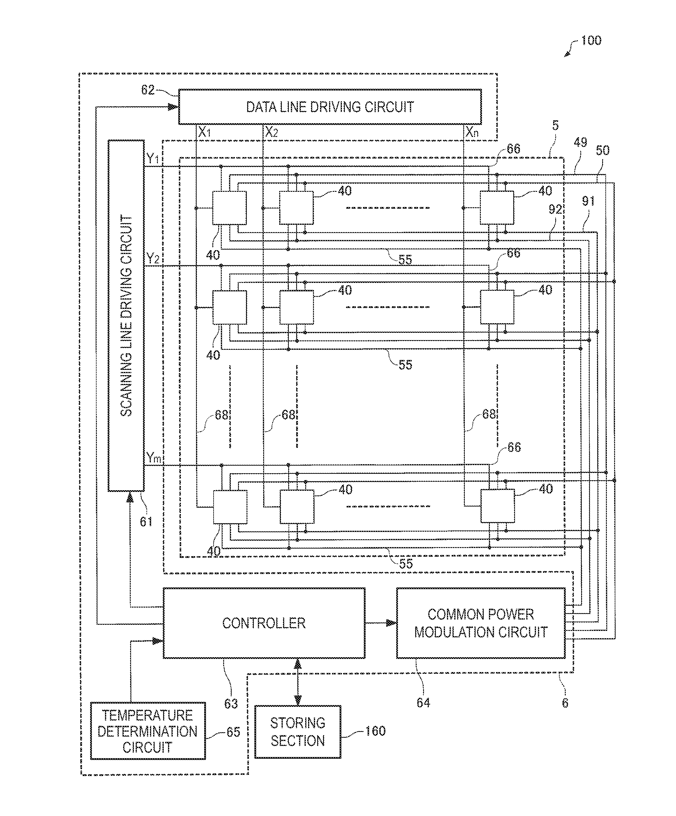
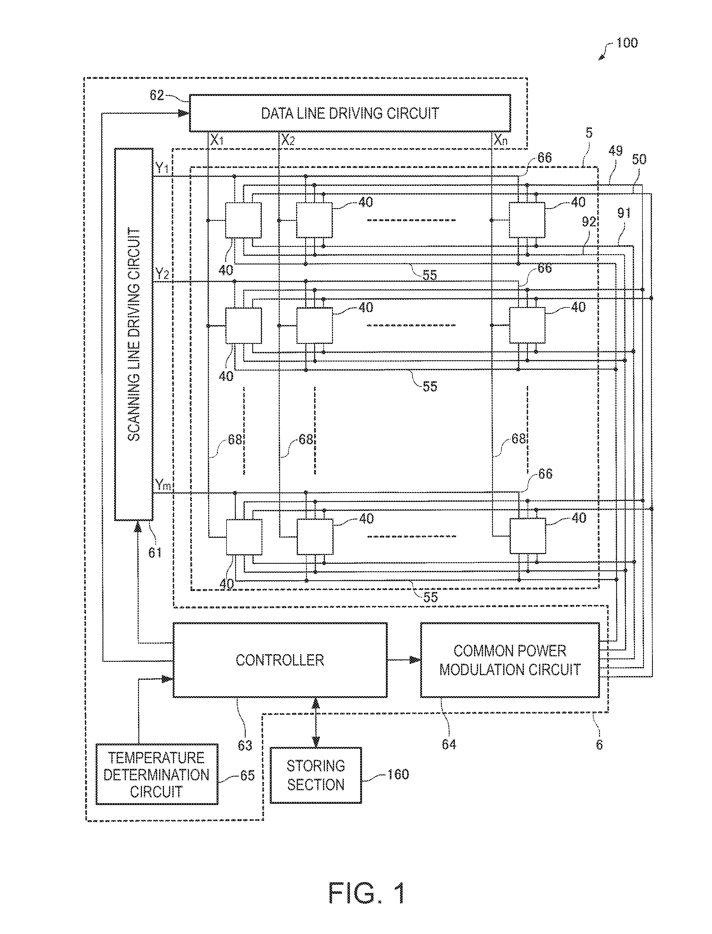
[0034]FIG. 1 is a block diagram illustrating an electrophoretic display device 100 of an active matrix drive type according to the present embodiment.

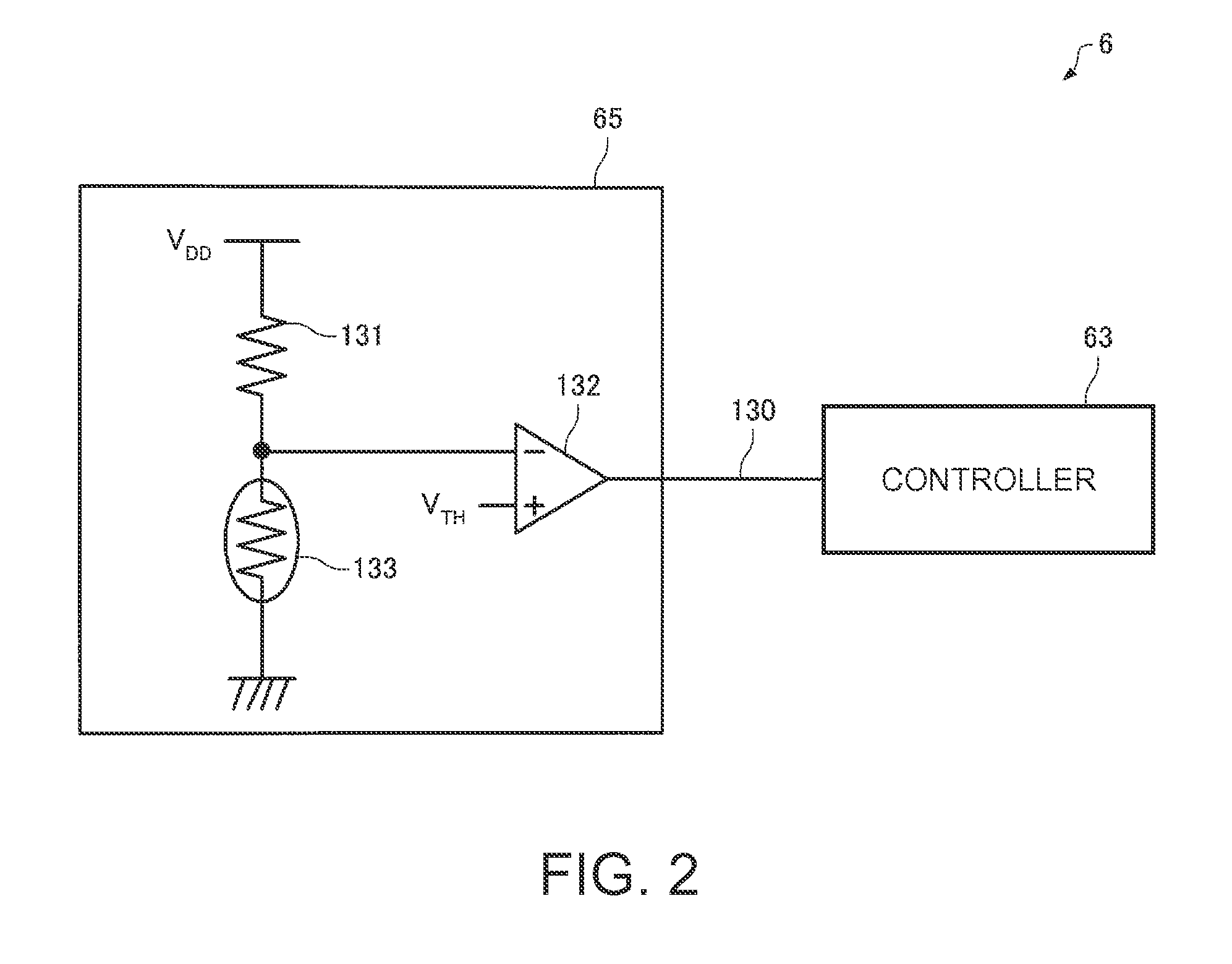
[0035]The electrophoretic display device 100 includes a control section 6, a storing section 160 and a display section 5. The control section 6 controls the display section 5, and includes a scanning line driving circuit 61, a data line driving circuit 62, a controller 63, a common power modulation circuit 64, and a temperature determination circuit 65. The scanning line driving circuit 61, the data line driving circuit 62, the common power modulation circuit 64, and the temperature determination circuit 65 are connected to the controller 63, respectively. The controller 63 generally controls these sections on the basis of image sign...

application example

2. Application example

[0088]An application example of the invention will be described with reference to FIGS. 10A and 10B. The electrophoretic display device 100 may be applied to a variety of electronic apparatuses.

[0089]For example, FIG. 10A is a front view of a wrist watch 1000 which is a kind of electronic apparatus. The wrist watch 1000 includes a watch case 1002 and a pair of bands 1003 connected to the watch case 1002. At a front portion of the watch case 1002, a display portion 1004 which includes the electrophoretic display device 100 is disposed, and the display section 1004 performs a display 1005 which includes a time display. At a side portion of the watch case 1002, two operation buttons 1011 and 1012 are disposed. A variety of display types such as time, calendar, alarm or the like may be selected as the display 1005 by the operation buttons 1011 and 1012.

[0090]Further, FIG. 10B is a perspective view of an electronic paper 1100 which is a kind of electronic apparatus,...


PUM


Abstract

An image rewriting process of rewriting an image displayed by applying any one of a first electric potential or a second electric potential to each of a plurality of pixel electrodes and by moving electrophoretic particles by an electric field generated between the pixel electrodes and a common electrode includes a temperature determining process, and includes a first pulse application process which uses the driving pulse signal with the pulse width being a first width, a low temperature pulse application process, and a second pulse application process which uses the driving pulse signal with the pulse width being a second width, performed at the end. The low temperature pulse application process uses the driving pulse signal with the pulse width being the first width.

Description

CROSS-REFERENCE TO RELATED APPLICATION[0001]This application claims priority to Japanese Patent Application No. 2010-268765 filed on Dec. 1, 2010. The entire disclosure of Japanese Patent Application No. 2010-268765 is hereby incorporated by herein reference.BACKGROUND[0002]1. Technical Field[0003]The present invention relates to a driving method of an electrophoretic display device, an electrophoretic display device, and an electronic apparatus.[0004]2. Related Art[0005]In recent years, a display panel having a memory ability, which is capable of retaining an image even though power is cut off, has been developed and used for an electronic watch or the like. As the display panel having the memory ability, an EPD (electrophoretic display) device, a liquid crystal display device having a memory ability, or the like has been proposed.[0006]In the electrophoretic display device, it is known that flickering occurs if driving is performed using a signal having a long pulse width at an in...

Claims


Application Information

Patent Timeline
IPC IPC(8): G09G5/00G09G3/34
CPCG09G3/344G09G2320/066G09G2320/041G09G2300/0857
Inventor MURAYAMA, TETSURO
Owner SEIKO EPSON CORP
Why Eureka
Try Eureka