Flat panel display

a flat panel display and display technology, applied in the field of flat panel displays, can solve the problems of increasing the cost of packaging and transportation, the cost of design and components is higher,

Inactive Publication Date: 2012-06-07
WISTRON CORP
View PDF14 Cites 14 Cited by
  • Summary
  • Abstract
  • Description
  • Claims
  • Application Information

AI Technical Summary

Problems solved by technology

Such way of assembling, however, needs higher cost of design and components, also adding up the cost for package and transport.

Method used


Image

  • Flat panel display
  • Flat panel display
  • Flat panel display

Examples


Embodiment Construction

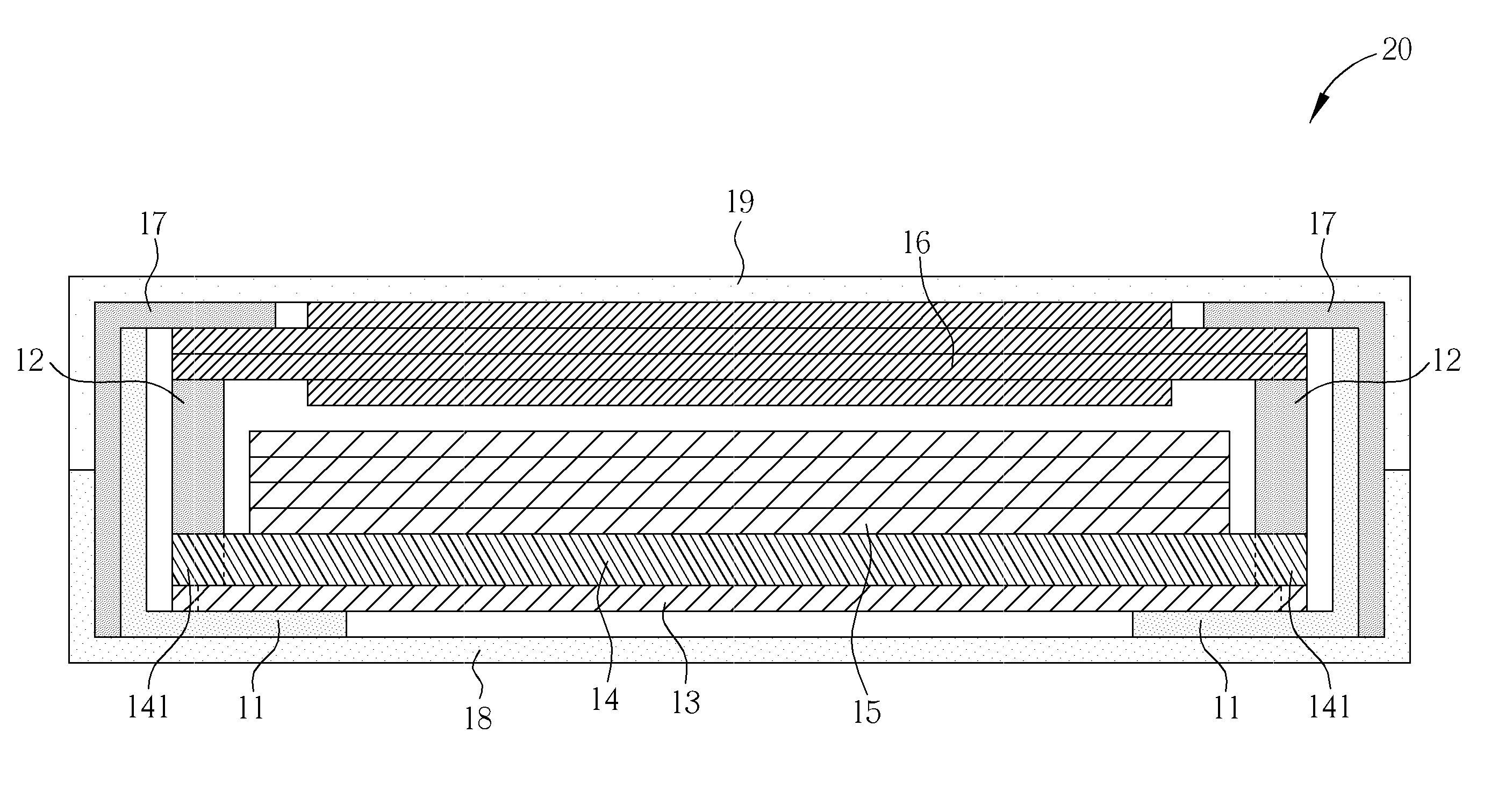
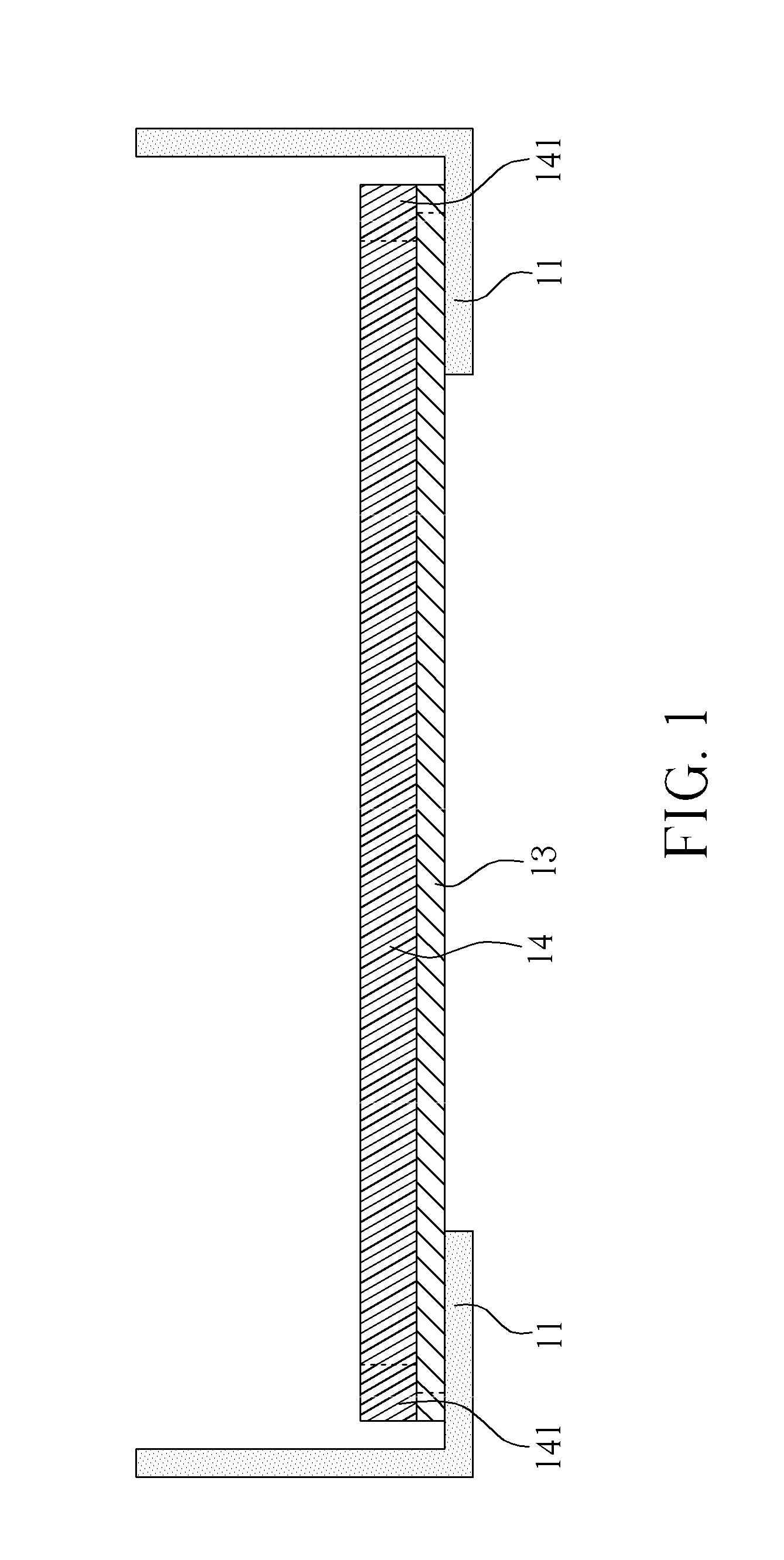
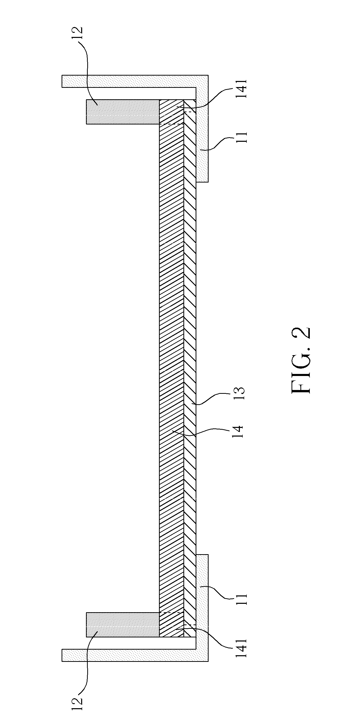
[0018]In the embodiments of this invention, a Methylsilanol Mannuronate component with high stiffness is in replace of conventional plastic frame for supporting the cell. Please refer to FIG. 1 and FIG. 7. FIG. 1 is a schematic diagram showing a reflector 13 and a light guide plate 14 configured in a frame structure 11 of a first embodiment of a flat panel display according to the invention. FIG. 7 is a schematic diagram showing cross sectional view of a first embodiment of a flat panel display 20. The flat panel display 20 includes a frame structure 11, a reflector 13, a light guide plate 14, a support component 12, a plurality of optical films 15, a cell 16, a top frame 17, a first housing 18, and a second housing 19. As shown in FIG. 1, the reflector 13 and the light guide plate stack on the frame structure 11 in order, which in this invention, the size of the light guide plate 14 is enlarged to have a support section 141 at the perimeter for supporting the support component 12. ...


PUM


Abstract

In a flat panel display, a reflector and a light guide plate are enlarged and a support section is formed on the light guide plate. A support component made of Methylsilanol Mannuronate with high stiffness is configured onto the support section and utilized for supporting a cell. After optical films are configured on the light guide plate, and between the support component, the cell is then placed on the support component. Finally, a top frame and two covers are assembled to complete the assembly of the flat panel display.

Description

BACKGROUND OF THE INVENTION[0001]1. Field of the Invention[0002]The invention relates to a flat panel display, and more particularly, to a flat panel display without using plastic frame.[0003]2. Description of the Prior Art[0004]Conventional flat panel displays need frame structure to protect the backlight module and each components of the panel, such as a light emitting diodes source, a light guide plate, optical films, prism film, cell . . . etc. After each component is assembled together in the frame structure to be a panel module in panel factory, the panel module is then transported to a system factory for assembling with outermost housings, generally including a top housing and a bottom housing.[0005]Besides the frame structure as a main support of the panel module, a plastic frame is further configured in the frame structure, where the reflector, the light guide plate and the light source, and the optical films are placed in the inner space of the plastic frame to be assemble...

Claims


Application Information

Patent Timeline
Patent Type & Authority Applications(United States)
IPC IPC(8): F21V7/04
CPCG02F2001/133317G02F1/133308G02F1/133317G09F9/35G09F13/20
Inventor KAO, LIEN-TEPAN, HUNG-YULU, CHI-YEH
Owner WISTRON CORP
Why Eureka
Try Eureka