
Slide rail structure

Active Publication Date: 2012-06-07
FULIAN PRECISION ELECTRONICS (TIANJIN) CO LTD
View PDF8 Cites 6 Cited by
  • Summary
  • Abstract
  • Description
  • Claims
  • Application Information

AI Technical Summary

Benefits of technology

[0004]Slide rail structures are widely used in many devices, such as drawers. Many slide rail structures include a first rail, a second rail, and a third rail. Slide mechanisms disposed between the first rail, the second rail, and the third rail include a ball-type structure and a friction-type structure. The ball-type structure can be smoothly slid, but is more costly. The friction-type structure has lower cost and better bearing capacity, but does not slide smoothly.

Problems solved by technology

The ball-type structure can be smoothly slid, but is more costly.
The friction-type structure has lower cost and better bearing capacity, but does not slide smoothly.

Method used


Image

  • Slide rail structure
  • Slide rail structure
  • Slide rail structure

Examples


Embodiment Construction

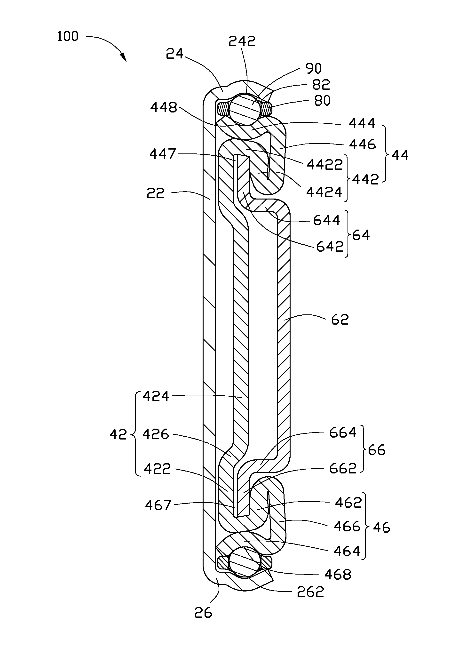
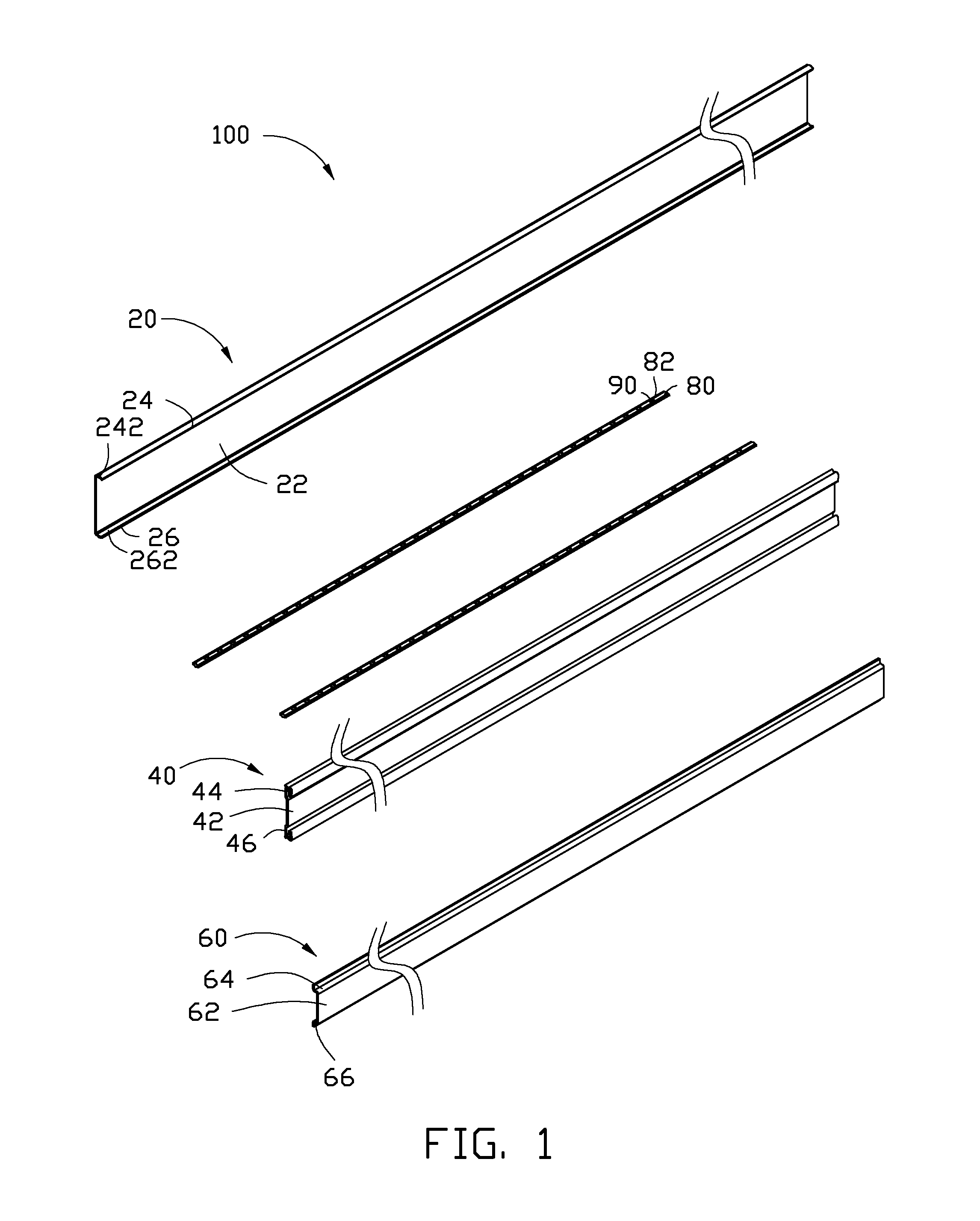
[0010]FIG. 1 is an exploded perspective view of an exemplary embodiment of a slide rail structure 100. The slide rail structure 100 includes a first rail 20, a second rail 40, a third rail 60, and two bearing seats 80 including bearings 90. The first rail 20 is attached to a fixture, such as a server cabinet or a cupboard. The third rail 60 is fixed on the walls of the server cabinet or a drawer of the cupboard.

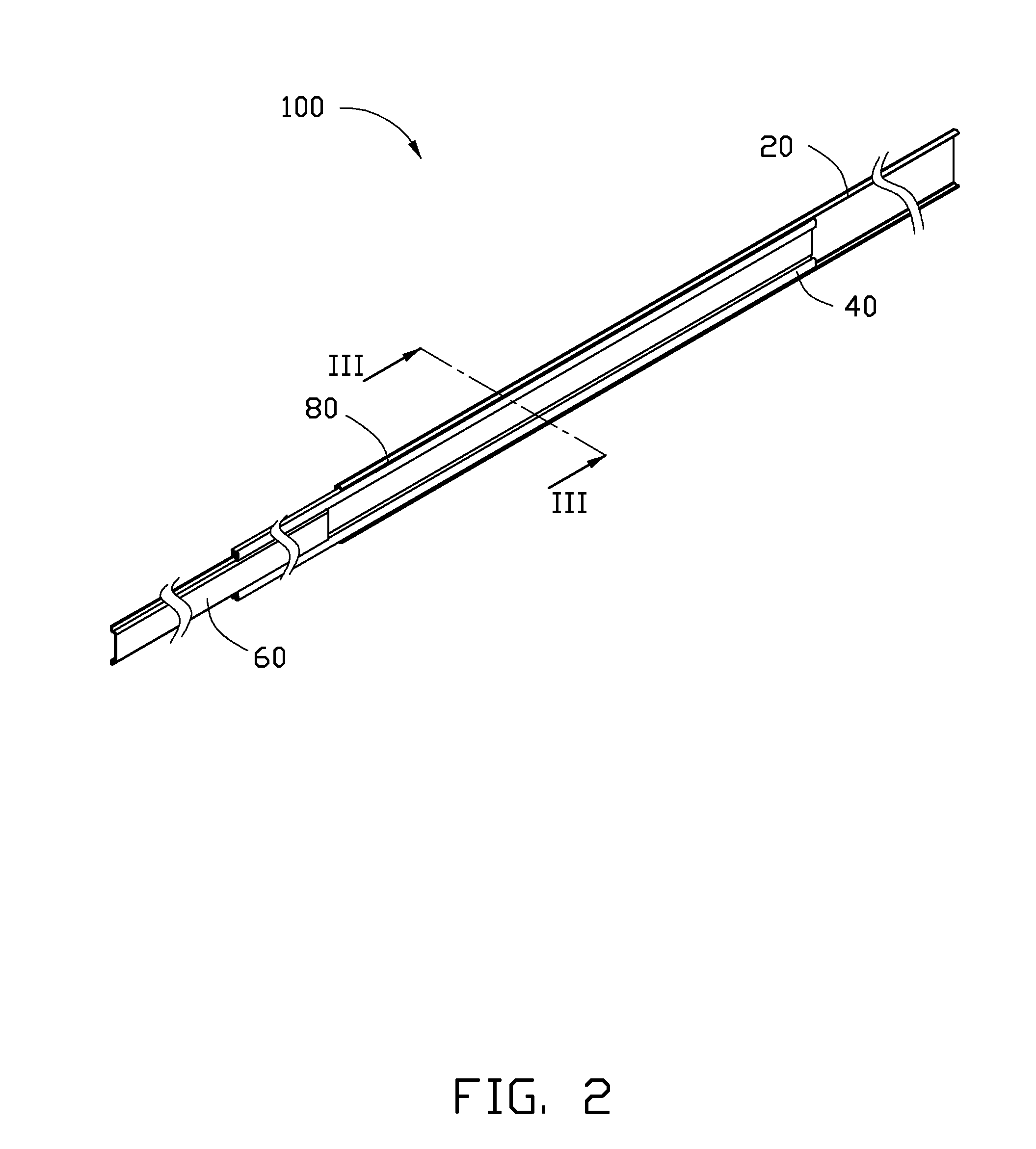
[0011]FIG. 2 is an assembled view of FIG. 1. The second rail 40 is received between the first rail 20 and the third rail 60. The two bearing seats 80 are disposed between the first rail 20 and the second rail 40. The second rail 40 can slide relative to the first rail 20 via the bearings 90. The third rail 60 slidably contacts the second rail 40 to slide relative to the second rail 40. As a result, the server and the drawer can be moved into and out of the server cabinet and the cupboard.

[0012]FIG. 3 is a sectional view of FIG. 2 taken along line III-III. The first rail 20 in...


PUM


Abstract

A slide rail structure includes a first rail, a second rail, a third rail, and two bearing seats including bearings. The bearing seat is disposed between the first rail and the second rail. The second rail is received between the first rail and the third rail. The second rail slides relative to the first rail via the bearings. The third rail slidably contacts the second rail.

Description

BACKGROUND[0001]1. Technical Field[0002]The present disclosure relates to a slide rail structure.[0003]2. Description of Related Art[0004]Slide rail structures are widely used in many devices, such as drawers. Many slide rail structures include a first rail, a second rail, and a third rail. Slide mechanisms disposed between the first rail, the second rail, and the third rail include a ball-type structure and a friction-type structure. The ball-type structure can be smoothly slid, but is more costly. The friction-type structure has lower cost and better bearing capacity, but does not slide smoothly.[0005]Therefore, there is room for improvement within the art.BRIEF DESCRIPTION OF THE DRAWINGS[0006]Many aspects of the present disclosure can be better understood with reference to the following drawings. The components in the various drawings are not necessarily drawn to scale, the emphasis instead being placed upon clearly illustrating the principles of the present disclosure. Moreover...

Claims


Application Information

Patent Timeline
IPC IPC(8): F16C17/26
CPCH05K7/1489
Inventor YU, MO-MINGCHEN, ZE-HONG
Owner FULIAN PRECISION ELECTRONICS (TIANJIN) CO LTD
Learn More