Intelligent coupler

Inactive Publication Date: 2012-06-07
TECHNOLOGICAL RESOURCES
View PDF7 Cites 8 Cited by
  • Summary
  • Abstract
  • Description
  • Claims
  • Application Information

AI Technical Summary

Benefits of technology

[0014]In another embodiment according to the invention, there is provided a method of testing an antenna coupler, the antenna coupler being configured to test a radio frequency electronic system of a unit under test. The method comprises uploading to a test set a radio frequency signature from a radio frequency signature storage component of the antenna coupler, the radio frequency signature comprising radio frequency test output comprising baseline confidence test output unique to the antenna coupler; emitting through a radio frequency test probe a radio frequency test input to the antenna coupler, thereby inducing radio frequency test output to be detected by a radio frequency confidence test device coupled to the antenna coupler; and comparing the radio frequency output from the radio frequency confidence test device with the uploaded radio frequency signature to assess performance of the antenna coupler relative to the baseline confidence test output unique to the antenna coupler.
[0015]In further, related embodiments, the method may comprise rejecting the antenna coupler performance if performance varies by more than a pre-specified amount from the baseline confidence test output unique to the antenna coupler. The pre-specified amount may comprise a limit that is plus or minus approximately 1 dB or less from the baseline confidence test output. The limit may be plus or minus approximately ½ dB from the baseline confidence test output. Uploading the radio frequency signature may be performed during production testing of the antenna coupler and/or during testing of the antenna coupler subsequent to deployment of the antenna coupler.
[0016]In another embodiment according to the invention, there is provided a method of testing a radio frequency electronic system of a unit under test. The method comprises uploading to a test set a radio frequency signature from a radio frequency signature storage component of the antenna coupler, the radio frequency signature comprising radio frequency test output; emitting through a probe of the antenna coupler a radio frequency test input to an antenna site of the unit under test, thereby inducing the production of radio frequency test output to be detected by the antenna coupler; and comparing the radi

Problems solved by technology

One of the unique challenges associated with antenna coupler design is the fact that antenna coupler antennas and RF system antennas are in close pro

Method used


Image

  • Intelligent coupler
  • Intelligent coupler
  • Intelligent coupler

Examples


Example

[0029]A description of example embodiments of the invention follows.

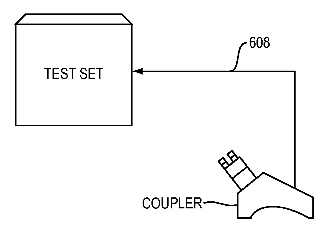
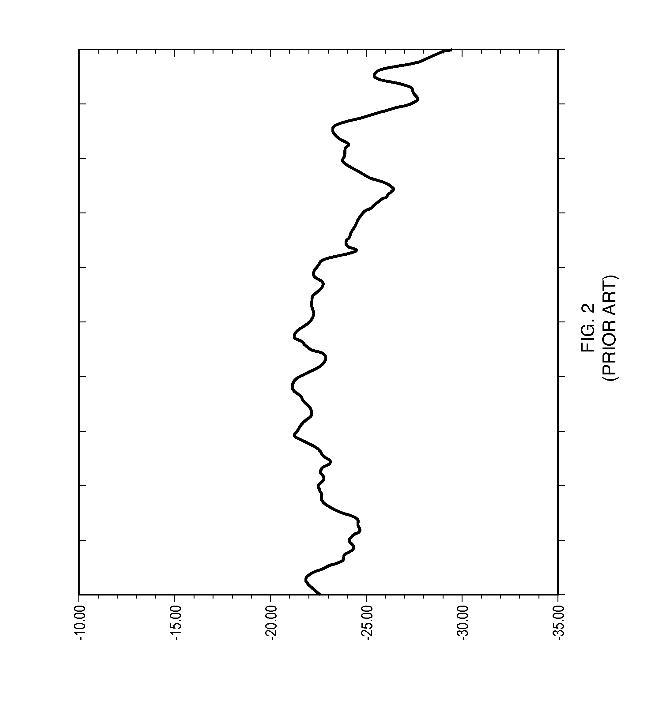
[0030]An embodiment according to the invention improves the radio frequency insertion loss performance of antenna couplers, for example to as little as + / −½ dB across broad band frequency ranges (several octaves), thus significantly improving the insertion loss tolerance in RF systems and antenna coupler self tests.

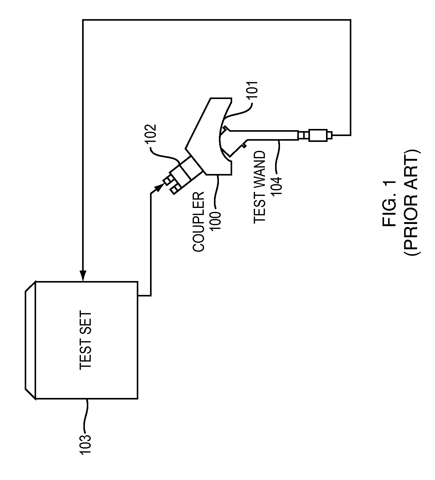
[0031]Presently, antenna couplers are generally used to perform two types of tests: a confidence test, which is a self-check of the antenna coupler to ensure that the antenna coupler and associated hardware are functioning correctly, and an RF coupling test, which is a test conducted on the unit under test to ensure that the unit under test's radio frequency systems are functioning correctly. Both types of tests, as presently performed, share some common features. Although embodiments are described herein with reference to the testing of electronic warfare systems installed in aircraft, it should be appre...


PUM


Abstract

In accordance with an embodiment of the invention, there is provided an antenna coupler for providing a radio frequency interface between a radio frequency electronic system of a unit under test and automatic test equipment for the radio frequency electronic system. The antenna coupler comprises a mechanical interface to secure the antenna coupler to an antenna site of the unit under test, and a radio frequency signature storage component comprising a stored representation of a radio frequency signature comprising radio frequency test output.

Description

RELATED APPLICATION[0001]This application claims the benefit of U.S. Provisional Application No. 61 / 418,709, filed on Dec. 1, 2010. The entire teachings of the above application are incorporated herein by reference.BACKGROUND OF THE INVENTION[0002]Antenna couplers are an integral element of test systems used to perform “end to end” tests of radio frequency (RF) systems, which may be embedded in various weapons platforms. The test system includes a test set, a test program set (typically implemented in software) and several antenna coupler types.[0003]The antenna couplers are RF interface devices that capture and transfer transmitted RF signals from the test set to the embedded RF system (receiver), and / or receive and transfer the transmitted signals from the RF transmitter embedded in the weapons platform to the test set. The antenna couplers are essential in the performance of end to end testing of embedded RF systems. Testing is performed external to the weapons platform, without ...

Claims


Application Information

Patent Timeline
IPC IPC(8): H04B17/00
CPCH01Q1/28G01R31/008G01R1/24G01R1/0408
Inventor VERMETTE, PAUL J.BURNS, ROBERT R.
Owner TECHNOLOGICAL RESOURCES
Why Eureka
Try Eureka