
Robot positioning method and calibration method

a positioning method and robot technology, applied in the field of robots, can solve the problems of increasing manufacturing costs, wasting a lot of time, and limited applications of robots, and achieve the effects of saving time, increasing calibration accuracy, and saving apparatus costs

Active Publication Date: 2012-06-07
IND TECH RES INST
View PDF2 Cites 13 Cited by
  • Summary
  • Abstract
  • Description
  • Claims
  • Application Information

AI Technical Summary

Benefits of technology

The present invention provides a robot positioning and calibration method using an optical sensing device and calibration plate. The technical effects include solving the problem of high apparatus cost and excessively long calibration time in the prior art. The method includes steps of capturing a calibration plate image by the optical sensing device, calculating a transformation matrix and optical sensing device-calibration plate coordinate value, and rotating and translating the robot to obtain the position of the optical sensing device in the calibration plate coordinate system. The method simplifies the calibration process and reduces the cost and time required for the same.

Problems solved by technology

However, most of the applications of the robots are still limited to dealing with repeated processes, and in this case, an experienced operator needs to manipulate a robot in advance to teach the robot to move along a fixed track.
In the miniature, diversified, and small-quantity production mode of the electronic industry, the method of teaching the robot by the operator in the automatic production may waste a lot of time, and the manufacturing cost is also increased.
Thus, it is a critical issue to be solved on how to establish a robot positioning method and calibration method to obtain a transformation matrix of the robot and the object and a distortion error value of the camera device.
However, the monitoring device in U.S. Pat. No.
'321 has a high apparatus cost.
'321, every time before the calibration of the robot, the monitoring device configured at the external side of the robot needs to be electrically connected to the robot, so that an additional time is required before the calibration to electrically connect the monitoring device to the robot, which increases the calibration procedure of the robot, and reduces the calibration efficiency of the robot.
'321 takes an excessively long calibration time.
'321, too much time is wasted before calibration, the apparatus cost is high, and the calibration time is too long.

Method used


Image

  • Robot positioning method and calibration method
  • Robot positioning method and calibration method
  • Robot positioning method and calibration method

Examples


Embodiment Construction

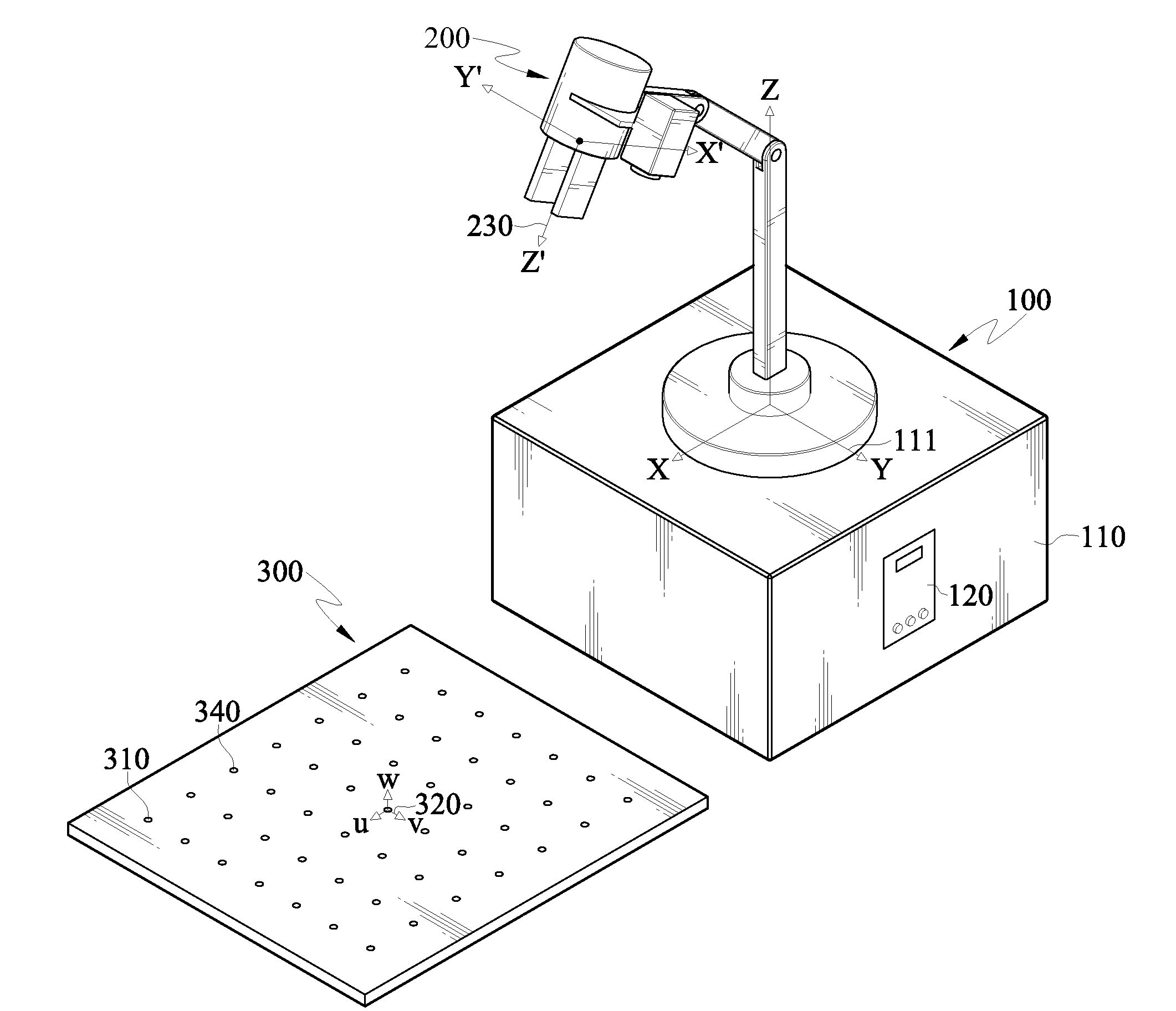
[0034]In an embodiment of the present invention, a robot calibration system is first provided. Referring to FIG. 8 to FIG. 9B, the robot calibration system comprises a robot 100, an optical sensing device 200, and a calibration plate 300. The robot 100 has a base 110 and a control unit 120. The optical sensing device 200 has, for example, a lens 210 and a CCD 220, the CCD 220 has an optical sensing surface 221, and multiple positioning marks 310 are disposed on a surface of the calibration plate 300. The base 110 has a base coordinate system 111, the optical sensing device 200 has an optical sensing device coordinate system 230, the optical sensing surface 221 has an optical sensing surface coordinate system 222, and the calibration plate 300 has a calibration plate coordinate system 320.

[0035]Based on the above robot 100, the optical sensing device 200, and the calibration plate 300, the present invention performs a positioning step, to obtain a relative position between the optica...


PUM


Abstract

A robot positioning method includes the following steps. A optical sensing device is configured at a front end of a robot. Then, the optical sensing device captures a calibration plate image, and a relative position of the optical sensing device with respective to a calibration plate is calculated according to a Bundle Adjustment. A robot calibration method includes the following steps. An optical sensing device is driven to rotate around a reference axis of a calibration plate, so as to calculate a translation matrix between the calibration plate and the robot, and the optical sensing device is driven to translate along three orthogonal reference axes of the calibration plate, so as to calculate a rotation matrix between the calibration plate and the robot.

Description

CROSS-REFERENCE TO RELATED APPLICATIONS[0001]This non-provisional application claims priority under 35 U.S.C. §119(a) on Patent Application No(s). 099142245 filed in Taiwan, R.O.C. on Dec. 3, 2010, the entire contents of which are hereby incorporated by reference.BACKGROUND OF THE INVENTION[0002]1. Field of Invention[0003]The present invention relates to a robot, and more particularly to a robot positioning method and calibration method.[0004]2. Related Art[0005]In the recent decade, robots are generally used in the industry to achieve automatic production. However, most of the applications of the robots are still limited to dealing with repeated processes, and in this case, an experienced operator needs to manipulate a robot in advance to teach the robot to move along a fixed track. In the miniature, diversified, and small-quantity production mode of the electronic industry, the method of teaching the robot by the operator in the automatic production may waste a lot of time, and th...

Claims


Application Information

Patent Timeline
Patent Type & Authority Applications(United States)
IPC IPC(8): B25J13/08
CPCG05B2219/39045B25J9/1692
Inventor SHIEH, PO-HUANGLU, SHANG-CHIEHJIANG, BOR-TUNGHUANG, KUO-TANGCHANG, CHIN-KUEI
Owner IND TECH RES INST
Learn More