

Switch unit and electronic device including switch unit
- Summary
- Abstract
- Description
- Claims
- Application Information
AI Technical Summary
Benefits of technology
Problems solved by technology
Method used
Image

Examples
Embodiment Construction
[0019]Various exemplary embodiments, features, and aspects of the invention will be described in detail below with reference to the drawings.
[0020]The first exemplary embodiment will be described. An exemplary embodiment of the present invention will be described in detail below based on appended drawings.
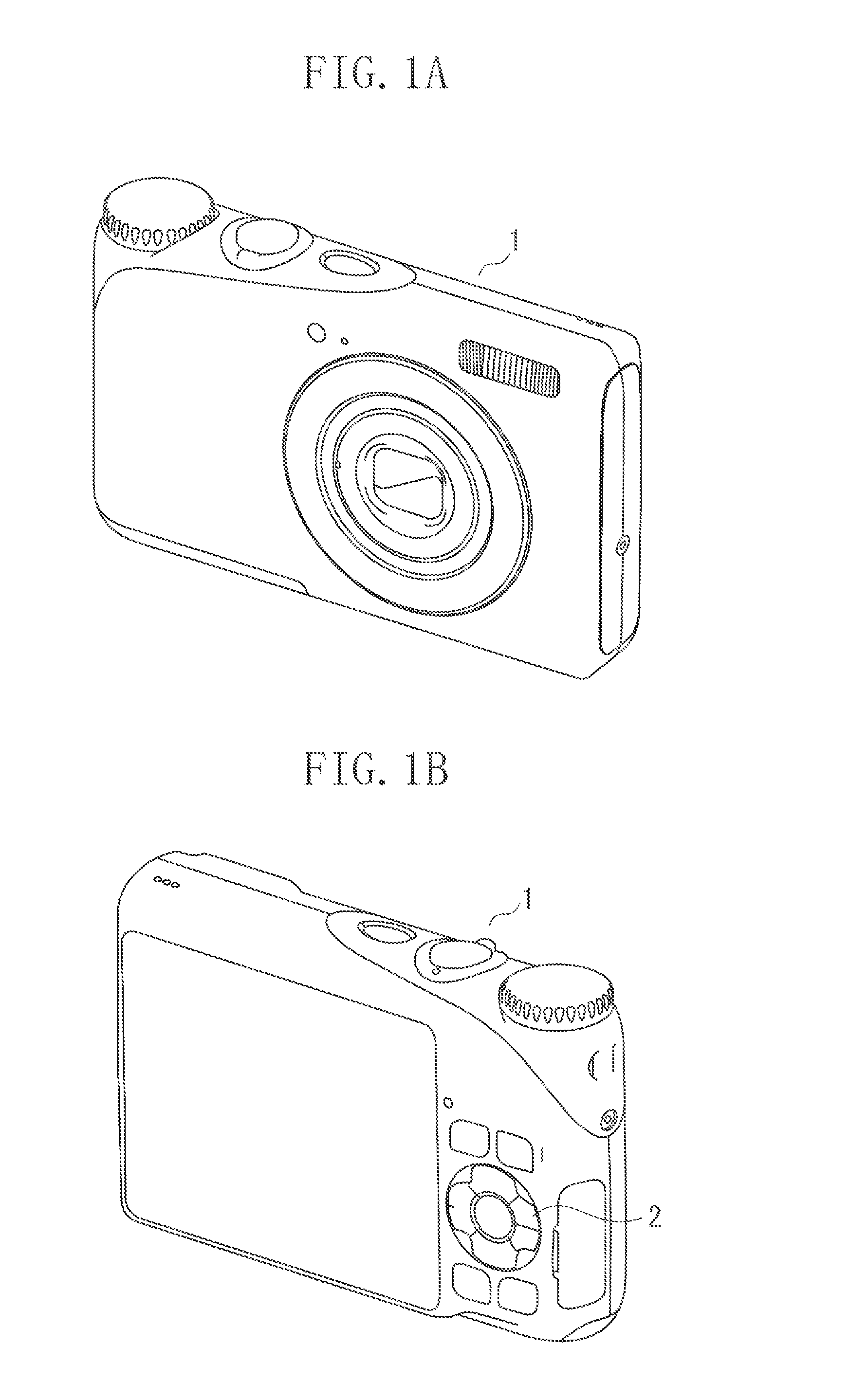
[0021]FIGS. 1A and 1B are external perspective views of a digital camera as an example of an electronic device including a switch unit embodying the present invention. FIG. 1A is an external perspective view viewed from the front side and FIG. 1B is an external perspective view viewed from the rear side.
[0022]A digital camera 1 in the present exemplary embodiment has operation buttons 2 to operate the camera and make various settings arranged on the rear side.
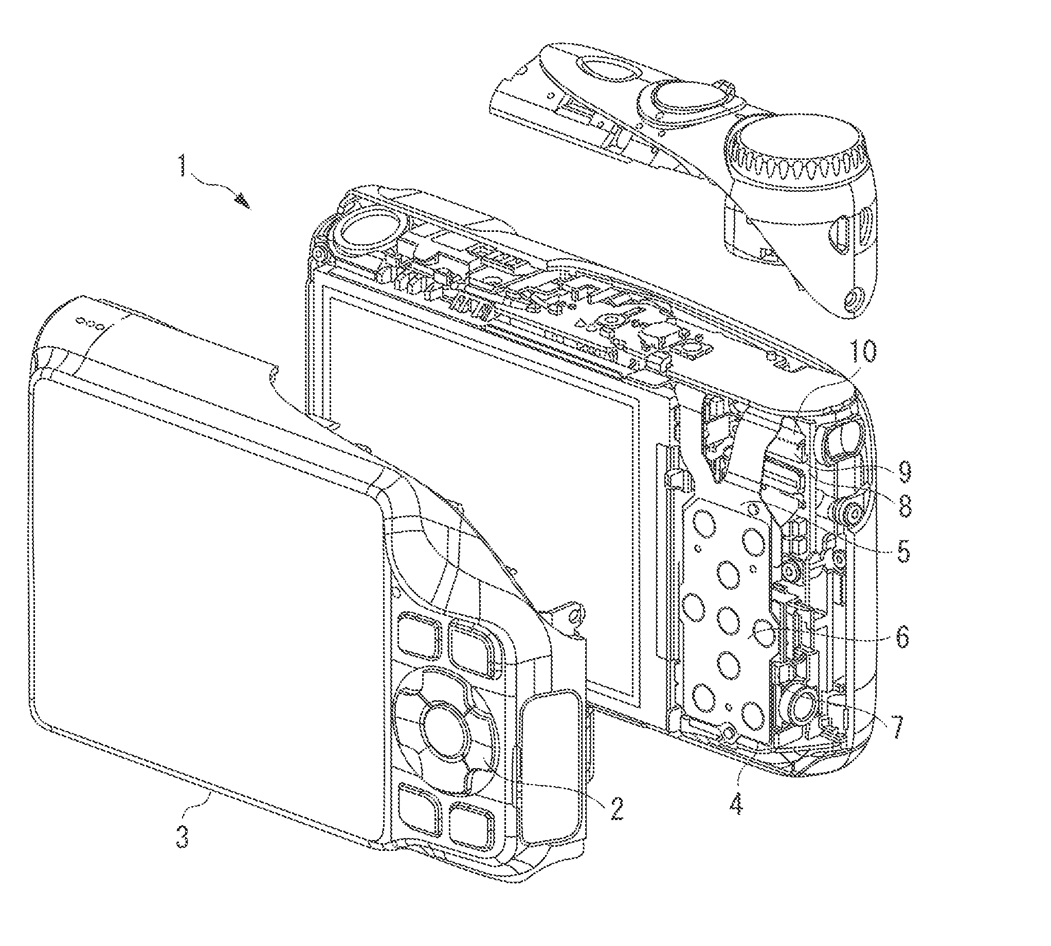
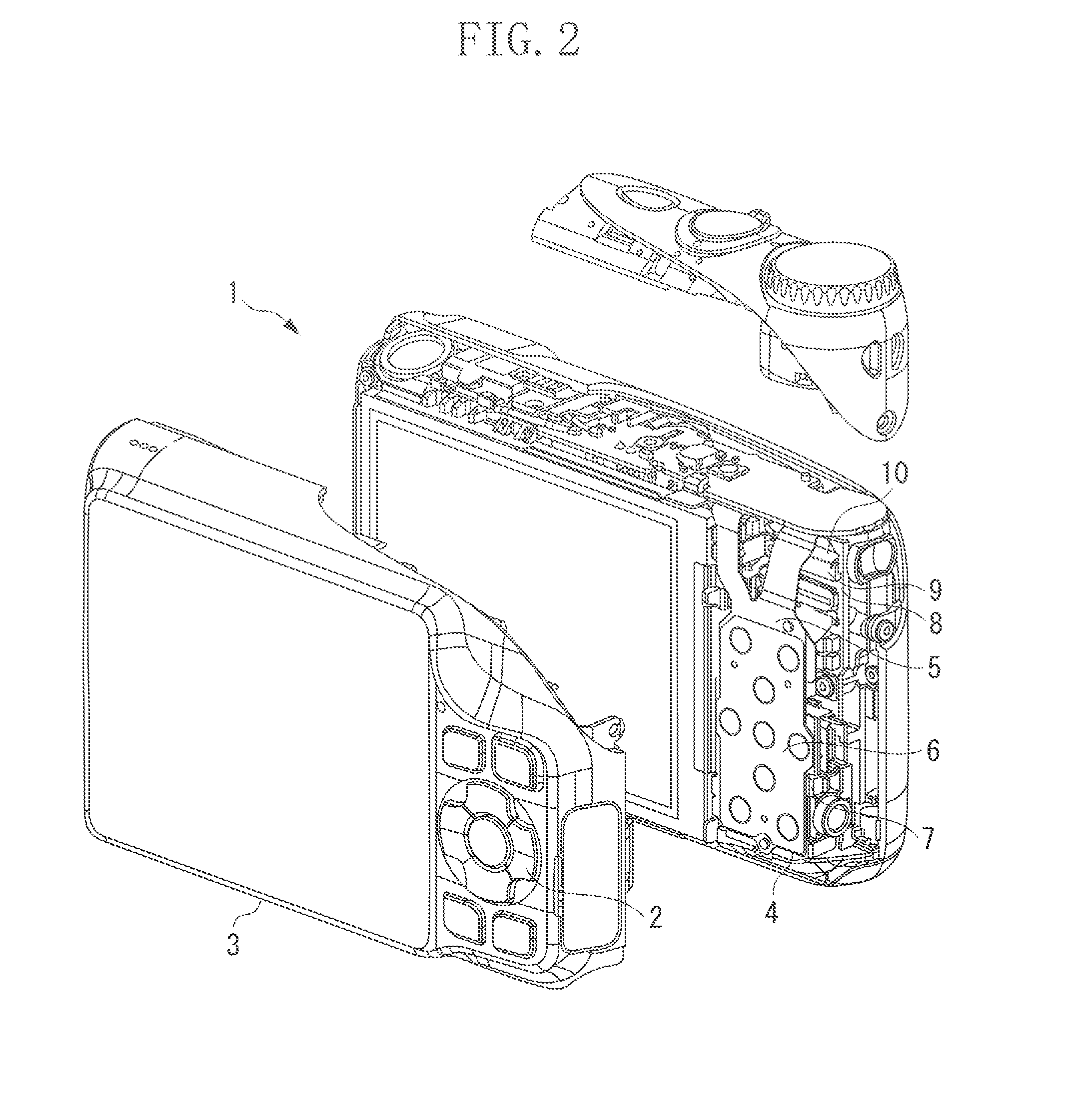
[0023]FIG. 2 is an exploded perspective view illustrating an internal constitution on the side of rear operation buttons of the digital camera 1 of FIGS. 1A and 1B.
[0024]A rear cover 3 has the operation buttons 2 set in a pred...
PUM
 Abstract
Description
Claims
Application Information