Vibration isolation apparatus

a technology of vibration isolation and rubber parts, which is applied in the direction of mechanical equipment, shock absorbers, transportation and packaging, etc., can solve the problems of inability to restrict the movement of the opponent member, damage, and collision between the opponent member and the bracket member, so as to improve the durability, reduce the contracting, and increase the rubber volume of the insert rubber part

Inactive Publication Date: 2012-06-14
TOYO TIRE & RUBBER CO LTD
View PDF13 Cites 10 Cited by
  • Summary
  • Abstract
  • Description
  • Claims
  • Application Information

AI Technical Summary

Benefits of technology

[0012]In this case, as shown in FIG. 37, separation resistance of the Lower mold A301 and the upper mold A302 of the rubber vulcanization mold A300 can be reduced by locating parting lines PL of the lower and upper molds A301 and A302 and the middle molds A303 at stopper surfaces (upper or lower side, that is, ends in separation directions of the lower and upper molds A301 and A302 in FIG. 37) of the covering rubber parts A053 as close as possible.
[0027]According to the vibration isolation apparatus of the fourth embodiment of the present invention, the rubber volume of the insert rubber part can be increased. Thus, since the rubber volumes of the protrusion rubber parts are smaller than the rubber volume of the insert rubber part, after a vulcanization process, the insert rubber part having a larger rubber volume is much contracted, and thus the protrusion rubber parts can be less contracted. As a result, the protrusion rubber parts which function as stopper members can have improved durability.

Problems solved by technology

However, in the case of such a vibration isolation apparatus of the related art, when an opponent member connected to the internal cylinder member is moved in a direction toward the bracket member, it is impossible to restrict the movement of the opponent member.
Thus, the opponent member and the bracket member may collide with each other and be damaged.

Method used


Image

  • Vibration isolation apparatus
  • Vibration isolation apparatus
  • Vibration isolation apparatus

Examples


first embodiment

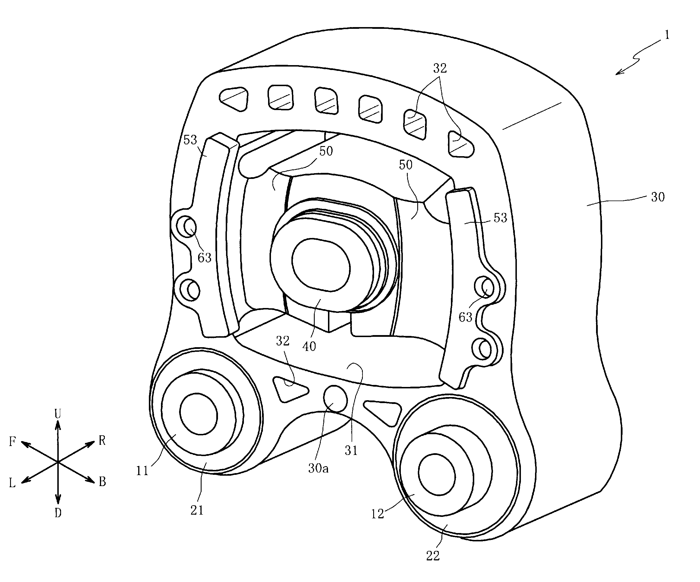
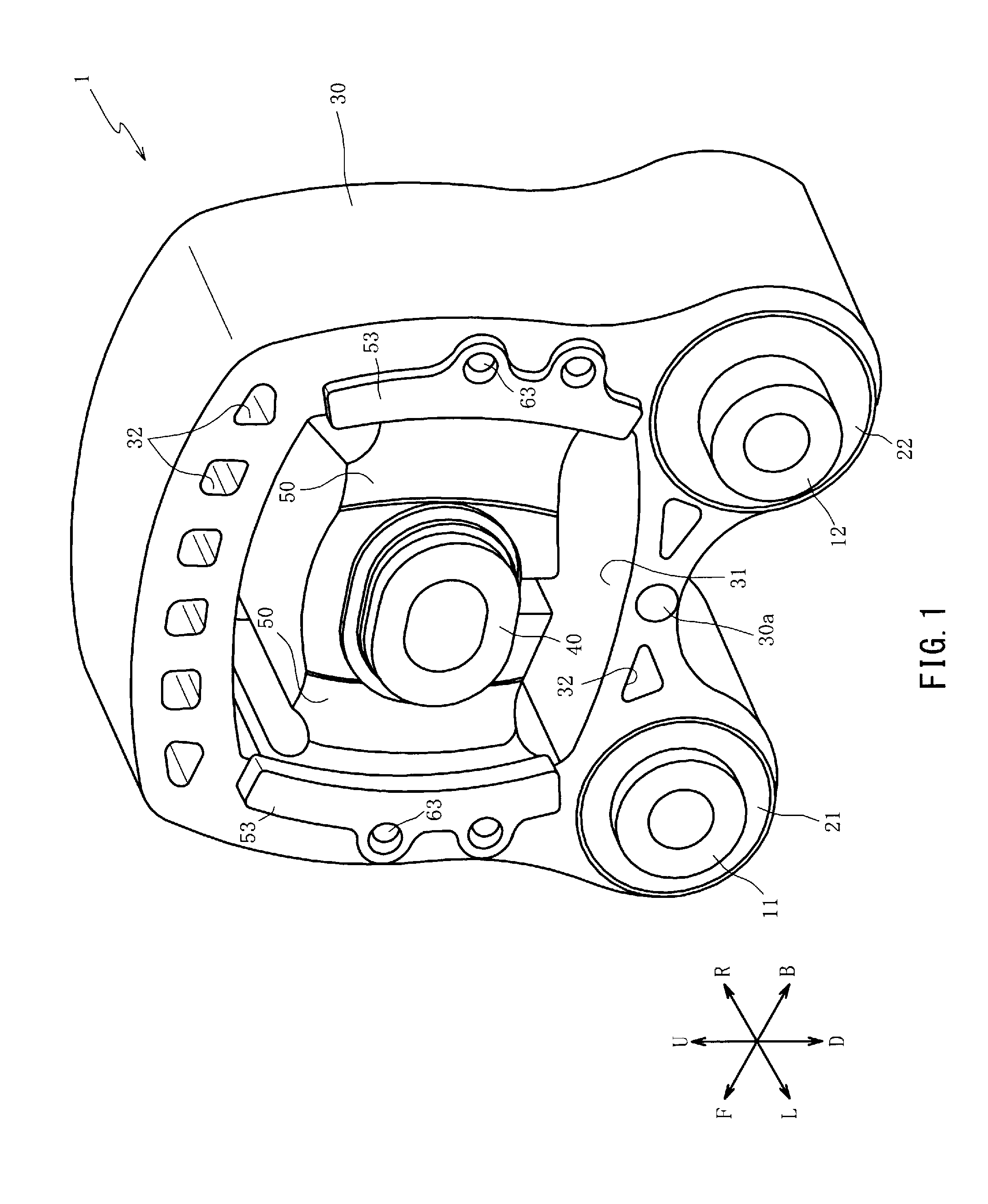
[0066]Hereinafter, preferred embodiments of the present invention will be described with reference to the accompanying drawings. First, the overall structure of a vibration isolation apparatus 1 will be described with reference to FIGS. 1, 2A, and 2B. FIG. 1 is a perspective view illustrating the vibration isolation apparatus 1 according to the present invention;

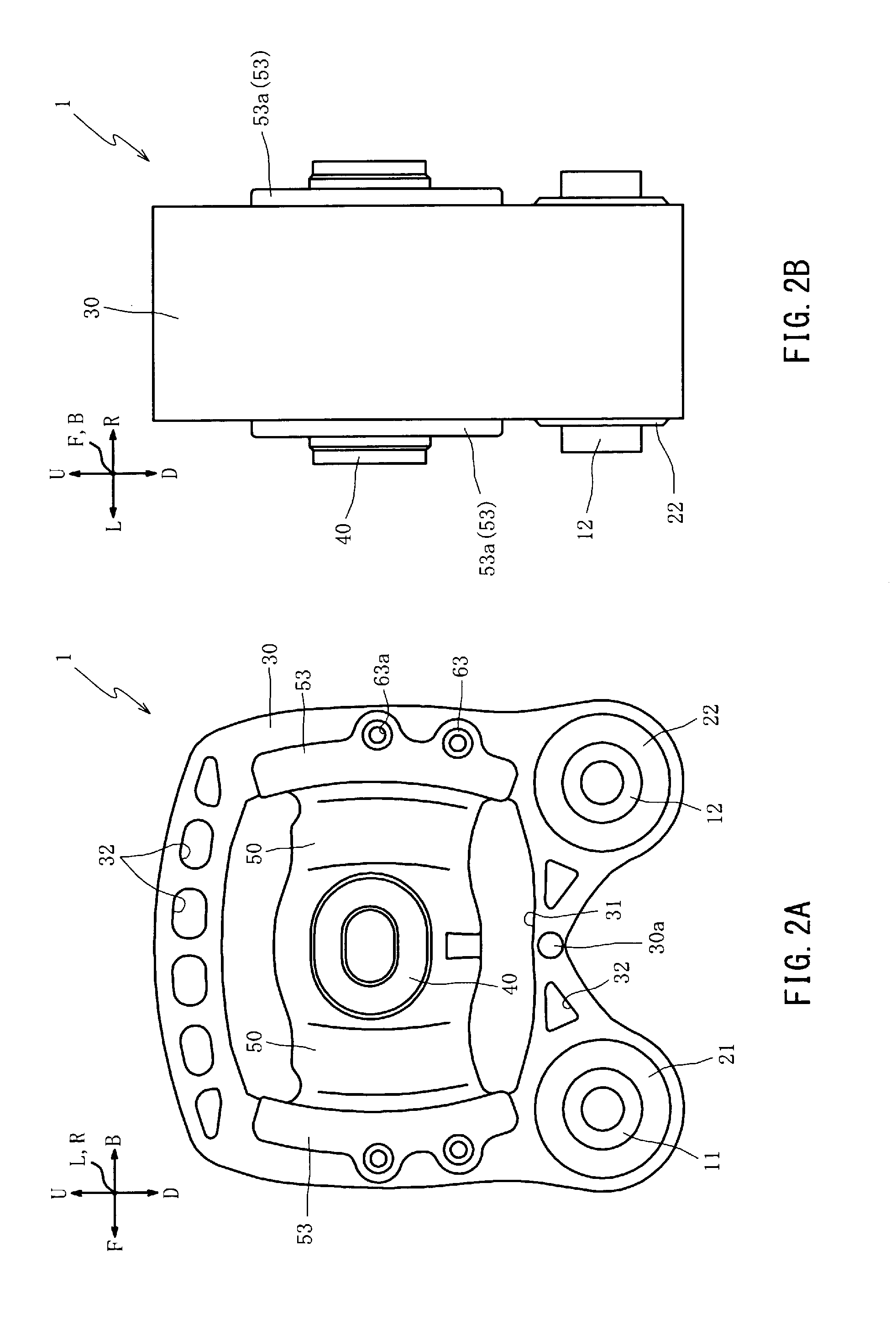
[0067]FIG. 2A is a front view illustrating the vibration isolation apparatus 1; and FIG. 2B is a side view illustrating the vibration isolation apparatus 1. In FIGS. 1, 2A, and 2B, the directions of arrows F and B denote the front and back directions of a vehicle, the directions of arrows L and R denote the left and right directions of the vehicle, and the directions of arrows U and D denote the upper and down directions of the vehicle.

[0068]As shown in FIGS. 1, 2A, and 2B, the vibration isolation apparatus 1 is used to support and fix a vehicle vibration source (not shown) and block transmission of vibration from the vibrat...

fourth embodiment

[0187]The base plate part 4061 includes a protrusion front part 4061b and a pair of protrusion side parts 4061c. The protrusion front part 4061b connects the pair of first wall parts 62. Along with this, the protrusion front part 4061b is curved in an arc-shaped sectional shape in a manner such that the height of the protrusion front part 4061b increases gradually from about the center of the base plate part 4061 to one of the first wall parts 62 (lower side in FIGS. 23A and 24A). Further, the protrusion front part 4061b protrudes toward an internal cylinder member 40 (refer to FIG. 25). The protrusion side parts 4061c are disposed on both sides of the protrusion front part 4061b (front and back sides of the paper in FIG. 24A) to connect the protrusion front part 4061b to the second wall parts 63. In addition, the protrusion side parts 4061c have a flat plate shape and extend from the second wall parts 63 to form the same planes together with the second wall parts 63, respectively. ...

fifth embodiment

[0199]Next, a first molding product 5100 of the fifth embodiment will be described with reference to FIGS. 28 and 29. FIG. 28 is a partially enlarged sectional view of the first molding product 5100. FIG. 28 corresponds to FIG. 7B. Further, FIG. 29 is a side view of the first molding product 5100 taken in the direction of an arrow XXIX of FIG. 28.

[0200]The first molding product 5100 of the fifth embodiment has the same structure as the first molding product 100 of the first embodiment except for a rubber notch 5055. Thus, the same elements are denoted by the same reference numerals, and descriptions thereof are not repeated.

[0201]As shown in FIGS. 28 and 29, the rubber notch 5055 is formed in one of first wall covering rubber parts 52. That is, since the first wall covering rubber parts 52 cover the outer surfaces of the first wall parts 62 to a constant thickness, the rubber notch 5055 slightly smaller than the fitting notch 5065 (by the covering thickness of rubber) is formed as a...


PUM

PropertyMeasurementUnit
elasticaaaaaaaaaa
distanceaaaaaaaaaa
areaaaaaaaaaaa

Abstract

Rubber burrs which are formed on a first molding product are set to the closer side of spaces of side surfaces. Therefore, when the first molding product is placed in a resin mold for a resin molding process, it is unnecessary to insert a rubber-burr portion in the resin mold at a predetermined position (at which protrusion rubber parts can be brought into tight contact with the resin mold for sealing). That is, the rubber burrs formed along the parting lines can be placed in a cavity of the resin mold. Therefore, since second rubber covering parts can be easily inserted in the resin mold at the predetermined positions and working time can be reduced, workability can be improved. Moreover, since the predetermined positions of the resin mold can be surely sealed by tight contact with the side faces, generation of resin burrs can be suppressed.

Description

CLAIM OF PRIORITY[0001]The present application claims of priority from Japanese patent application JP 2010-275157 filed on Dec. 9, 2011, the content of which is hereby incorporated by reference into this application.FIELD OF THE INVENTION[0002]The present invention relates to a vibration isolation apparatus in which a vibration isolation leg formed of a rubber-like elastic material is inserted in a bracket member formed of a resin material by insert molding in a state where a portion of the vibration isolation leg protrudes from the outer surface of the bracket member, and more particularly, to a vibration isolation apparatus configured to suppress generation of resin burrs and improve the workability when a vibration isolation leg is placed in a resin mold.BACKGROUND OF THE INVENTION[0003]For example, an example of known vibration isolation apparatuses is configured as follows: an inner hole is formed in a bracket member attached to a vehicle body; an internal cylinder member dispo...

Claims


Application Information

Patent Timeline
Patent Type & Authority Applications(United States)
IPC IPC(8): F16F7/00F16F3/087B29C65/70
CPCF16F1/3849B29C45/14065B29C45/1671B29C33/005B29C2045/14122B29C2045/1682
Inventor KATO, HIRONORITAKASHIMA, YUKIO
Owner TOYO TIRE & RUBBER CO LTD
Why Eureka
Try Eureka