Spring-elastic axial seal

a technology of axial seals and springs, applied in the field of seals, can solve the problems of more difficult displacement of bearing faces with respect to sealing faces, and achieve the effects of improving the sealing action of seals, reducing the risk of wavy profiles, and facilitating the bending of wavy profiles

Inactive Publication Date: 2012-06-14
ROBERT BOSCH GMBH
View PDF12 Cites 10 Cited by
  • Summary
  • Abstract
  • Description
  • Claims
  • Application Information

AI Technical Summary

Benefits of technology

[0007]Two spring elements are thereby connected in series in respect of the spring direction, so that a spring constant of the overall seal is lower than a spring constant of an individual spring element. Thus, operating, installation and manufacturing tolerances in the spring direction can be compensated, without major forces having to be exerted upon the sealing faces, which would result in making it more difficult for the bearing faces to be displaced with respect to the sealing faces.
[0008]The supporting element at the same time absorbs part of the shear forces which act in the lateral direction upon the seal during a displacement of a bearing face with respect to a sealing face, so that the seal is not appreciably deformed during displacement and leaktightness can be maintained. The spring elements can be designed to be integrated with the supporting element in the form of a wavy profile, with the result that the seal can be produced more easily. The wavy profile may have perforations in order to make it easier for the wavy profile to bend along the contour.
[0009]Each of the spring elements may comprise a U-shaped or V-shaped profile which runs along the contour. This simple embodiment is known from conventional seals and is tried and tested. Furthermore, in the event of a pressure drop between the inside and the outside of the contour, such a profile can be oriented such that the legs point in the direction of the high-pressure side. The pressure drop presses the legs of the spring element apart, with the result that the sealing action of the seal can be further improved.
[0010]The spring elements and the supporting element may be portions of a helical spring. This constitutes a further simple and cost-effective possibility for combining a low spring constant perpendicularly to the sealing faces with a good supporting action against shear forces running laterally with respect to the sealing faces.
[0011]The spring elements and the supporting element may alternatively also be portions of an elastic all-metal cushion made from knitted wire cloth, so that the seal also has a high thermal load-bearing capacity.

Problems solved by technology

Thus, operating, installation and manufacturing tolerances in the spring direction can be compensated, without major forces having to be exerted upon the sealing faces, which would result in making it more difficult for the bearing faces to be displaced with respect to the sealing faces.

Method used


Image

  • Spring-elastic axial seal
  • Spring-elastic axial seal
  • Spring-elastic axial seal

Examples


first embodiment

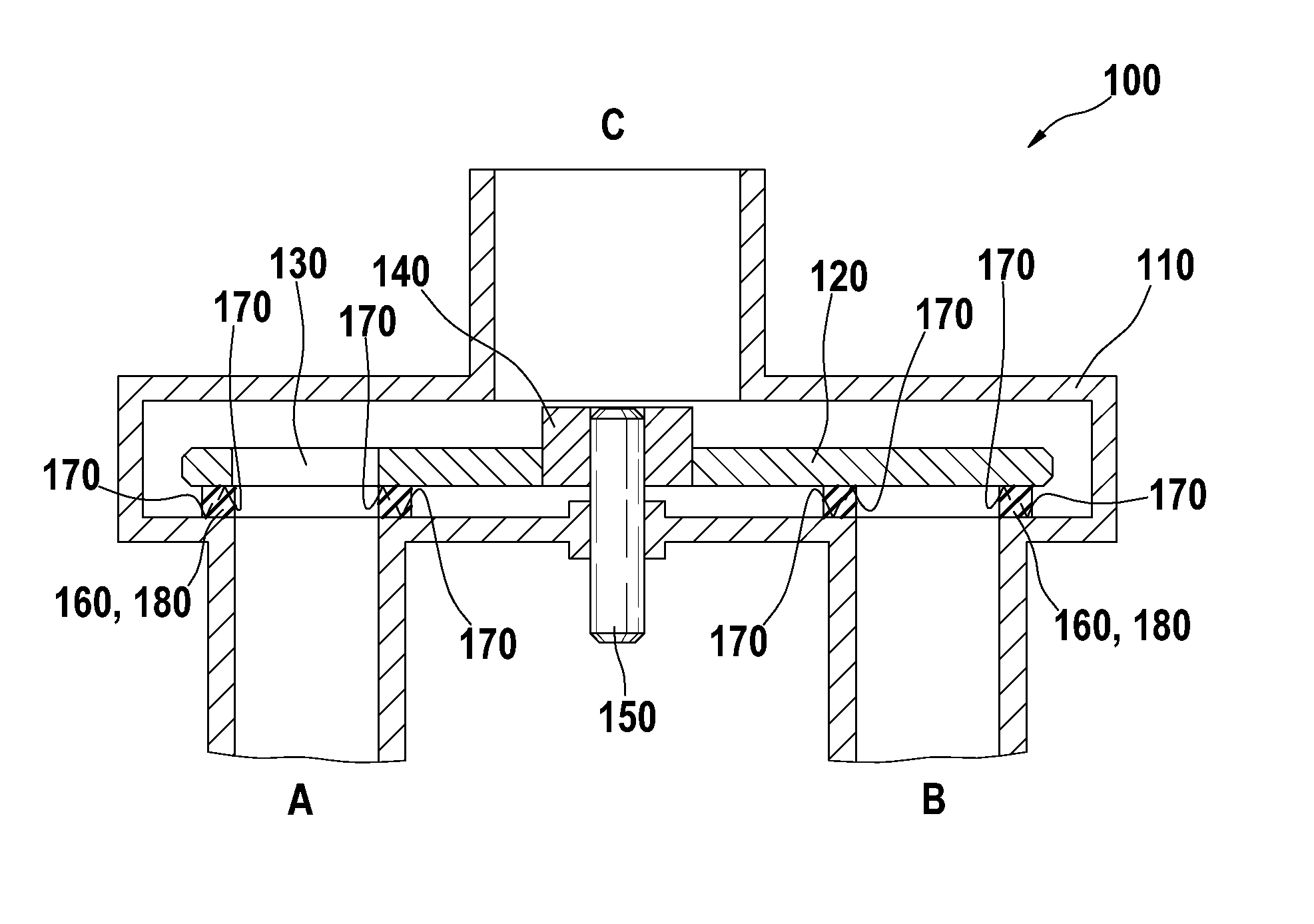
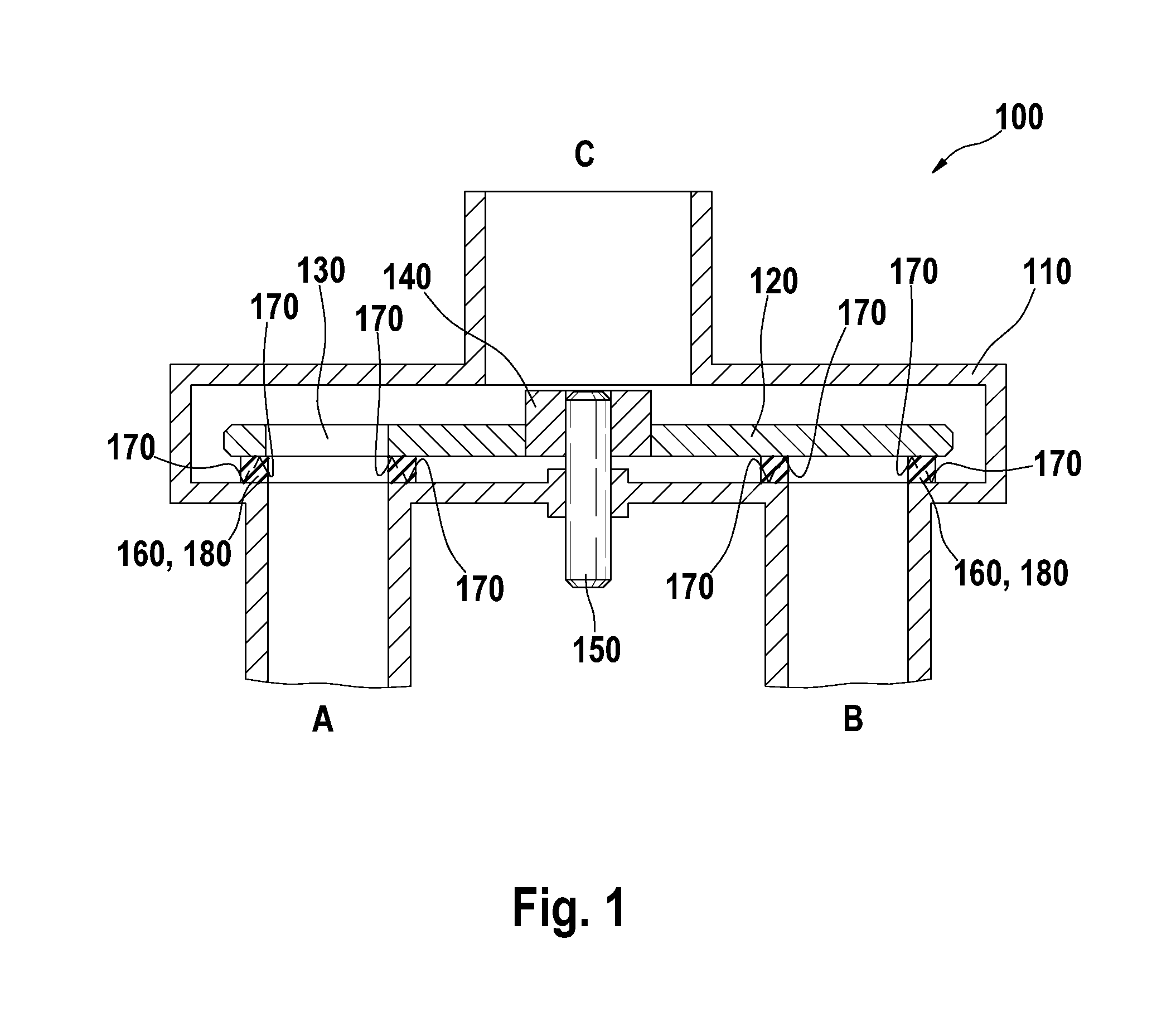
[0025]FIG. 2 shows a sectional view of a seal 160 for the valve 100 from FIG. 1. The seal 160 runs along the circular contour 180 (not depicted) which runs perpendicularly with respect to the drawing plane. For reasons of symmetry, only one sectional plane of the seal 160 is illustrated, and at the left margin of the drawing the bisecting line is depicted which at the same time forms a mid-axis of the contour 180.

[0026]The seal 160 comprises a sealing element 210, a first spring element 220 and a second spring element 230. The sealing element 210 has at the top and bottom in each case a sealing face 240 for contact with a bearing face 170 (not depicted). Between the spring elements 220 and 230 the sealing element 210 comprises a web 250. The sealing element 210 has at the top and bottom in each case a sealing lip, the removed boundary faces of which form the sealing faces 240. In the region of the upper sealing lip, the first spring element 230 is arranged in the form of a U-shaped ...

second embodiment

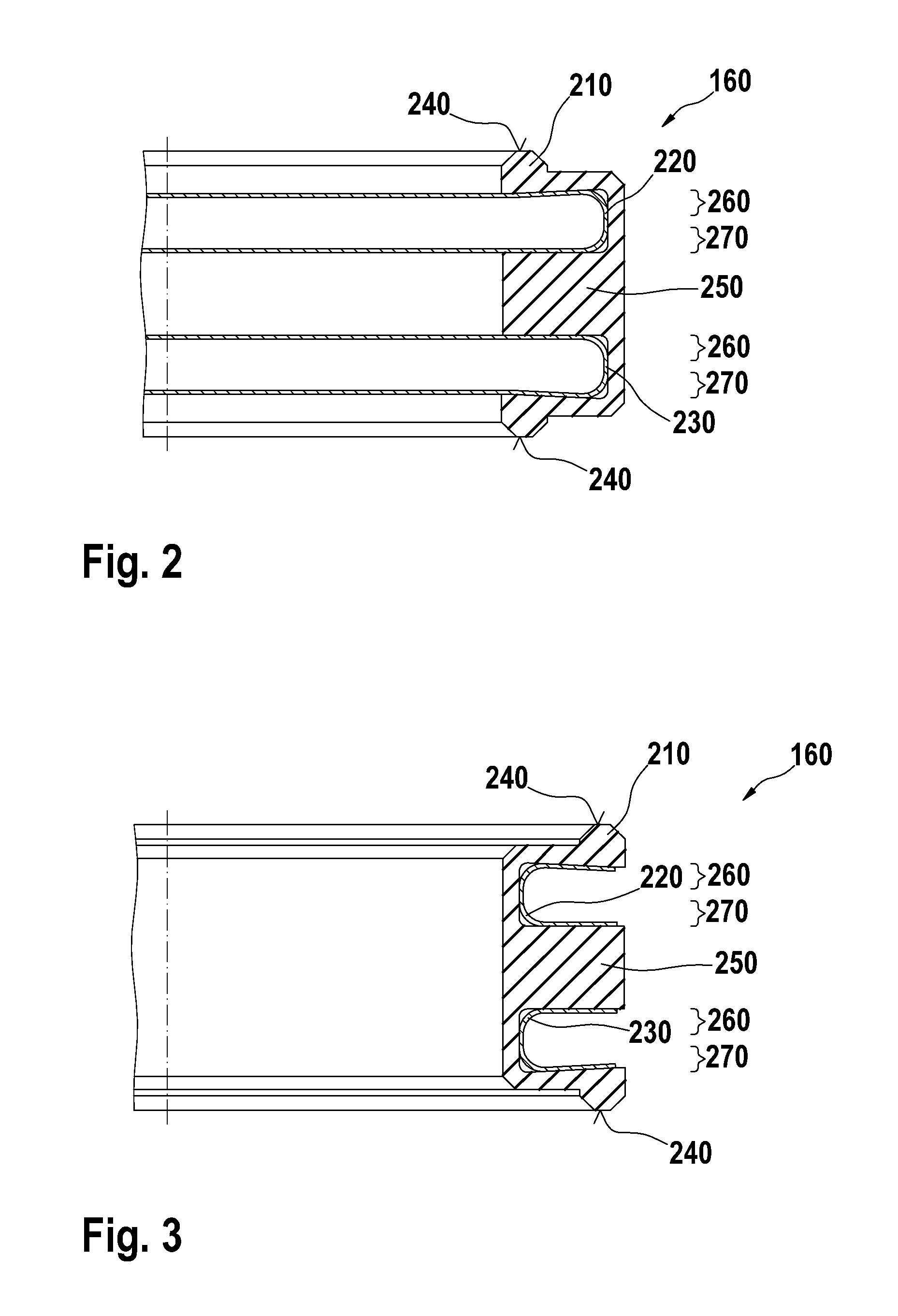
[0031]FIG. 3 shows a sectional view of a seal 160 for the valve 100 from FIG. 1. The embodiment illustrated corresponds to that from FIG. 2, the difference being that the legs 260, 270 of the U-shaped profiles of the spring elements 220 and 230 point outward and are covered inwardly by the sealing element 210. This type of construction is recommended in the case of a pressure drop from the outside inward, in order to increase a pressing action of the sealing faces 240 to the corresponding press-on faces by means of the pressure drop.

third embodiment

[0032]FIG. 4 shows a sectional view of a seal 160 for the valve 100 from FIG. 1. The seal illustrated is constructed in a similar way to the embodiment illustrated in FIG. 3, but, in contrast to the U-shaped spring elements 220 and 230 in FIG. 3, V-shaped spring elements 220, 230 composed of a V-shaped profile are used. These have a lower spring constant in the vertical direction than the spring elements 220, 230 composed of a U-shaped profile from FIGS. 2 and 3 and thus ensure a lower spring constant of the overall seal 160 in the vertical direction between the sealing faces 240.


PUM


Abstract

The invention relates to a seal (160) for sealing two opposite contact surfaces along a closed contour, comprising an elastic sealing element (210), which has two opposite sealing surfaces (240) to bear against the contact surfaces in the region of the contour, two spring elements (220, 230), each of which is associated with one of the sealing surfaces, and a supporting element (250) arranged between the spring elements, wherein each spring element comprises two limbs (260, 270), one limb pressing the sealing surface associated with the spring element against one of the contact surfaces and the other limb being supported on the supporting element.

Description

BACKGROUND OF THE INVENTION[0001]The invention relates to a seal. In particular, the invention relates to a seal for sealing off two bearing faces lying opposite one another.[0002]Sealing off bearing faces which lie opposite one another is necessary, for example, where slide valves are concerned. The planar surfaces of a valve body and of a sealing disk are mounted there parallel to one another with a clearance. An orifice in the valve body enables a fluid medium, for example a cooling liquid, to flow to the valve disk. The valve disk is arranged displaceably with respect to the valve body, for example linearly or rotatably, and has an orifice which is more or less in alignment with the orifice in the valve body, depending on the position of the valve disk. The orifices may, for example, have a round or elliptic cross section. Accordingly, a flow of a fluid medium through the valve disk is dependent upon its displacement position with respect to the valve body.[0003]In order to prev...

Claims


Application Information

Patent Timeline
Patent Type & Authority Applications(United States)
IPC IPC(8): F16J15/16
CPCF16J15/3236F16K11/074F16K3/08F16K3/0227
Inventor REEB, GEORGMUSCHELKNAUTZ, CLAUDIUS
Owner ROBERT BOSCH GMBH
Why Eureka
Try Eureka