Light guide plate with diffraction gratings and backlight module using the same

a technology of diffraction gratings and light guide plates, which is applied in the direction of lighting and heating apparatus, instruments, mechanical equipment, etc., can solve the problems of gratings being worn, generating spectral phenomena, and relatively low uniformity provided by projections, and achieves high light utilization efficiency and high uniformity of outgoing light.

Inactive Publication Date: 2005-06-09
HON HAI PRECISION IND CO LTD
View PDF11 Cites 27 Cited by
  • Summary
  • Abstract
  • Description
  • Claims
  • Application Information

AI Technical Summary

Benefits of technology

[0010] An object of the present invention is to provide a light guide plate for a backlight module

Problems solved by technology

However, the uniformity provided by projections is relatively low compared with light guide plates having gratings.
Nevertheless, there are two main problems associated with gratings.
Firstly, a grating is subject to becoming worn over time.
Secondly, a grating generates spectral phenomena.
However, in numerous actu

Method used


Image

  • Light guide plate with diffraction gratings and backlight module using the same
  • Light guide plate with diffraction gratings and backlight module using the same
  • Light guide plate with diffraction gratings and backlight module using the same

Examples


first embodiment

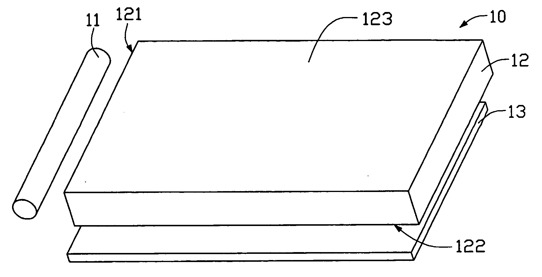
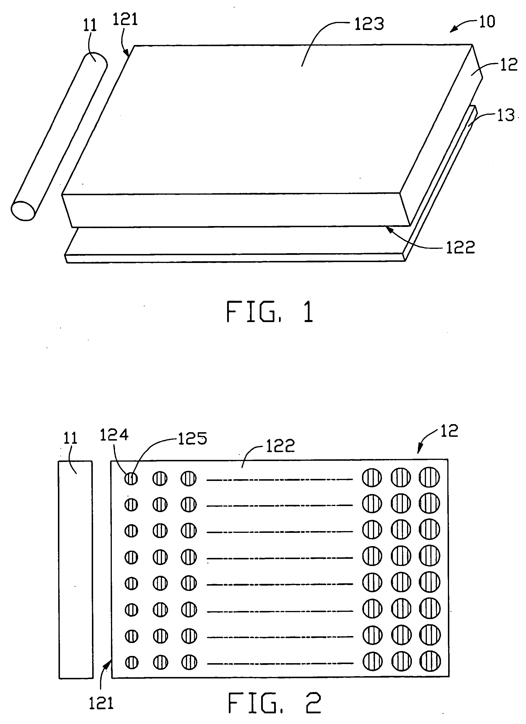
[0021] Referring to FIG. 1, a backlight module 10 according to the present invention is shown. The backlight module 10 comprises a linear light source 11, a transparent light guide plate-like member 12 having a rectangular cross-section, and a reflection plate 13 arranged under the light guide plate 12. The light guide plate 12 comprises a light emitting surface 123, a bottom surface 122 opposite to the light emitting surface 123, and a light incidence surface 121 adjoining both the light emitting surface 123 and the bottom surface 122. The light source 11 is a CCFL (cold cathode fluorescent lamp) disposed adjacent the light incidence surface 121. The reflection plate 13 is disposed under the bottom surface 122.

[0022] Referring to FIG. 2, a plurality of diffusion elements 124 is arranged at the bottom surface 122 for diffusing light beams. Each diffusion element 124 defines a diffraction grating unit 125 therein. Grating constants of the diffraction grating units 125 are in the rang...

second embodiment

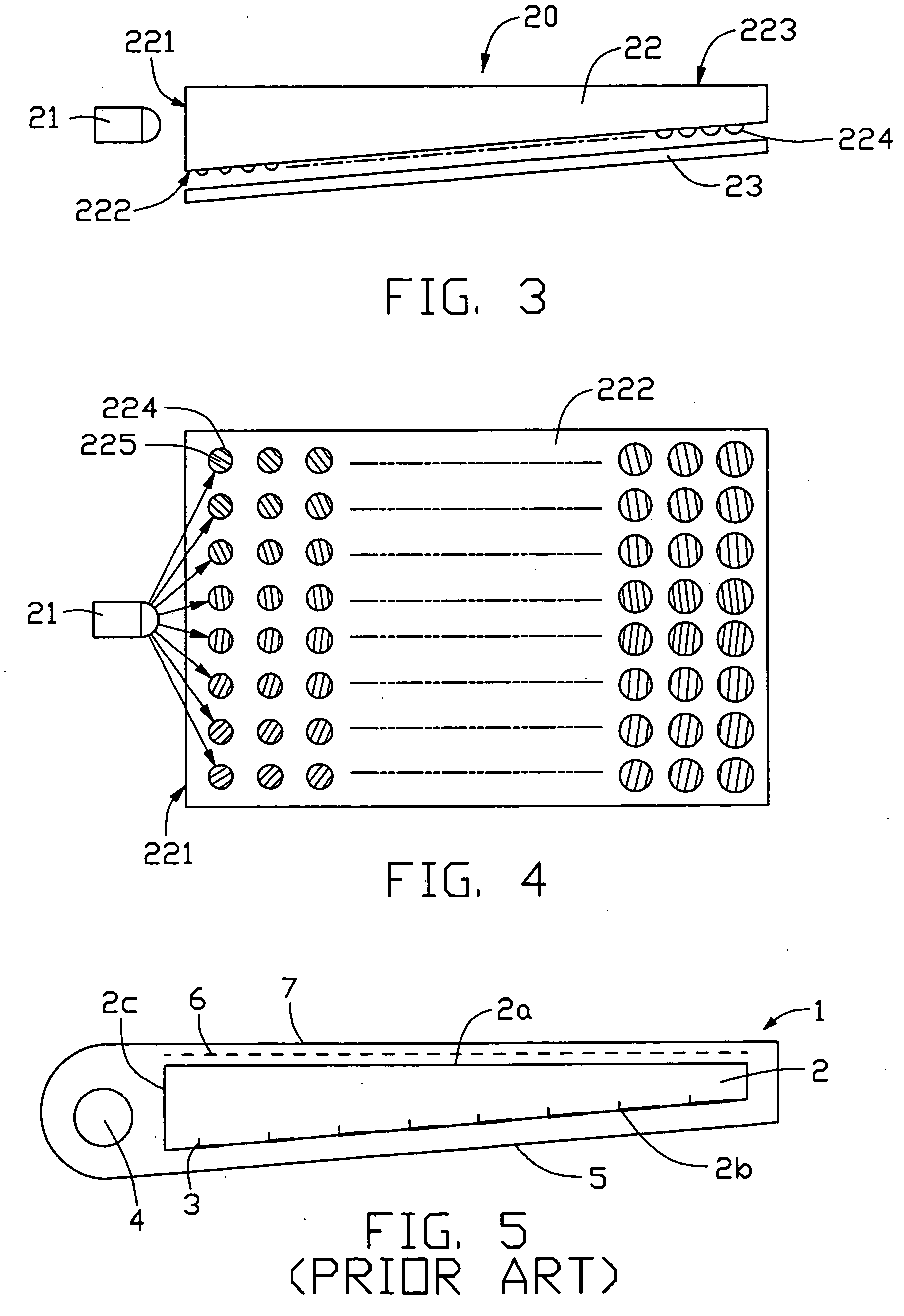
[0025] Referring to FIG. 3, a backlight module 20 according to the present invention is shown. The backlight module 20 comprises a light source 21, a transparent wedgy light guide plate 22, and a reflection plate 23. The light guide plate 22 comprises a light incidence surface 221, a light emitting surface 223, and a bottom surface 222 opposite to the light emitting surface 223. The light source 21 is an LED (light emitting diode), and is disposed adjacent the light incidence surface 221. In alternative embodiments, two or more LEDs can be employed as the light source 21. The reflection plate 23 is disposed under the bottom surface 222. A plurality of diffusion elements 224 is formed on the bottom surface 222, for diffusing light beams.

[0026] Referring to FIG. 4, each diffusion element 124 defines a diffraction grating unit 225 thereon. Grating constants of the diffraction grating units 225 are in the range from 2-5 μm, and preferably 3 μm. Because the light source 21 is an LED, the...


PUM


Abstract

A light guide plate (12) has a light incidence surface (121) for receiving light, a light emitting surface (123) for emitting light, and a bottom surface (122). The bottom surface has a plurality of diffusion elements (124) arranged thereat. Each diffusion element defines a diffraction grating unit (125) therein. A grating direction of each diffraction grating unit is substantially perpendicular to a main direction of light beams received by the diffraction grating unit. Areas of the diffraction grating units progressively increase with increasing distance away from the light incidence surface. Diffractive capabilities of the diffraction grating units progressively increase with increasing distance away from the light incidence surface. These features improve the overall efficiency of utilization of light, and enable the light emitting surface to output highly uniform light.

Description

BACKGROUND OF THE INVENTION [0001] 1. Field of the Invention [0002] The present invention relates to a light guide plate utilizing diffraction gratings for controlling of light emission, and to a backlight module for a liquid crystal display using such a light guide plate. [0003] 2. Description of Prior Art [0004] A typical liquid crystal display requires a backlight module in order to be able to provide uniform illumination. The performance of the backlight module greatly depends on a light guide plate employed therein. Means for enhancing the uniformity of light that is output from a light guide plate can be classified into two categories. The first category uses geometrical optical means, such as prisms or micro projections. The second category uses wave optical means, such as diffraction gratings. Light guide plates with multifarious configurations of micro projections and prisms have been developed, and some of these light guide plates can generate quite uniform light beams. Ho...

Claims


Application Information

Patent Timeline
IPC IPC(8): F21V8/00G02B6/00
CPCG02B6/0046G02B6/0043
Inventor LIN, JHY-CHAIN
Owner HON HAI PRECISION IND CO LTD
Why Eureka
Try Eureka