
Electronic Ballast with High Power Factor
a technology of electronic ballast and power factor, which is applied in the direction of electric lighting sources, light sources, lighting apparatus, etc., can solve the problems of low cost, dimmability of fluorescent lamps, and large circuit size that is incompatible with the size of a cfl, and achieves low cost. , the effect of reducing the current stress across the switch and reducing the loss of the switch
- Summary
- Abstract
- Description
- Claims
- Application Information
AI Technical Summary
Benefits of technology
Problems solved by technology
Method used
Image

Examples
working examples
1. Electronic Ballast Circuit
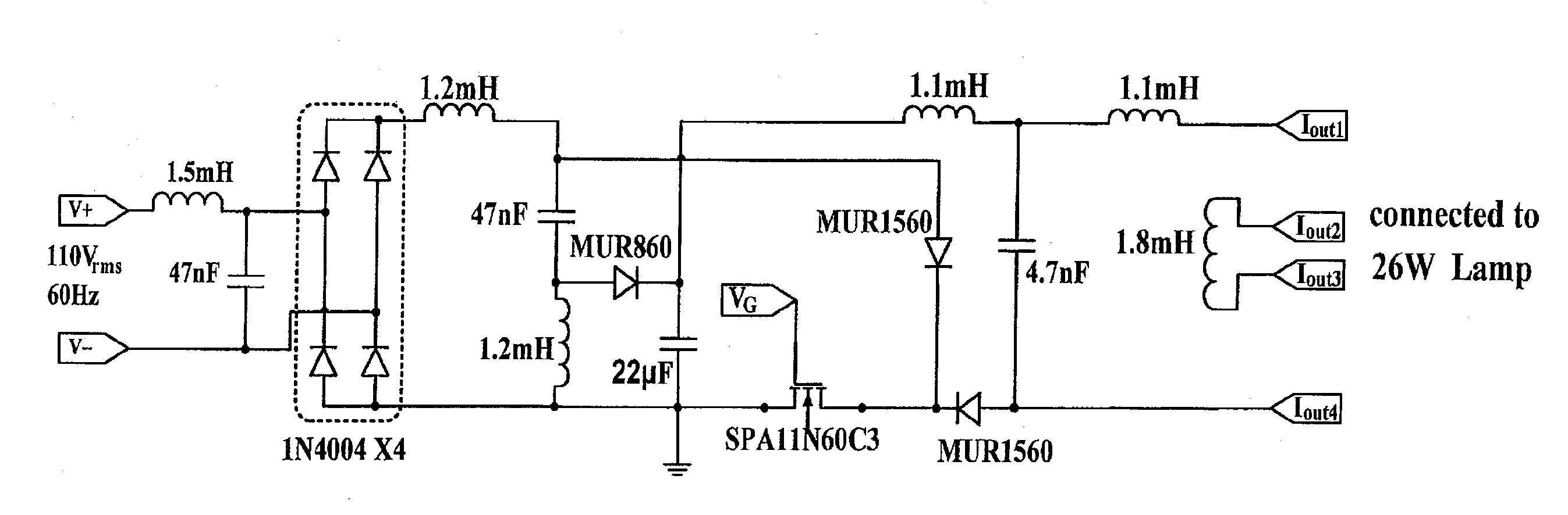
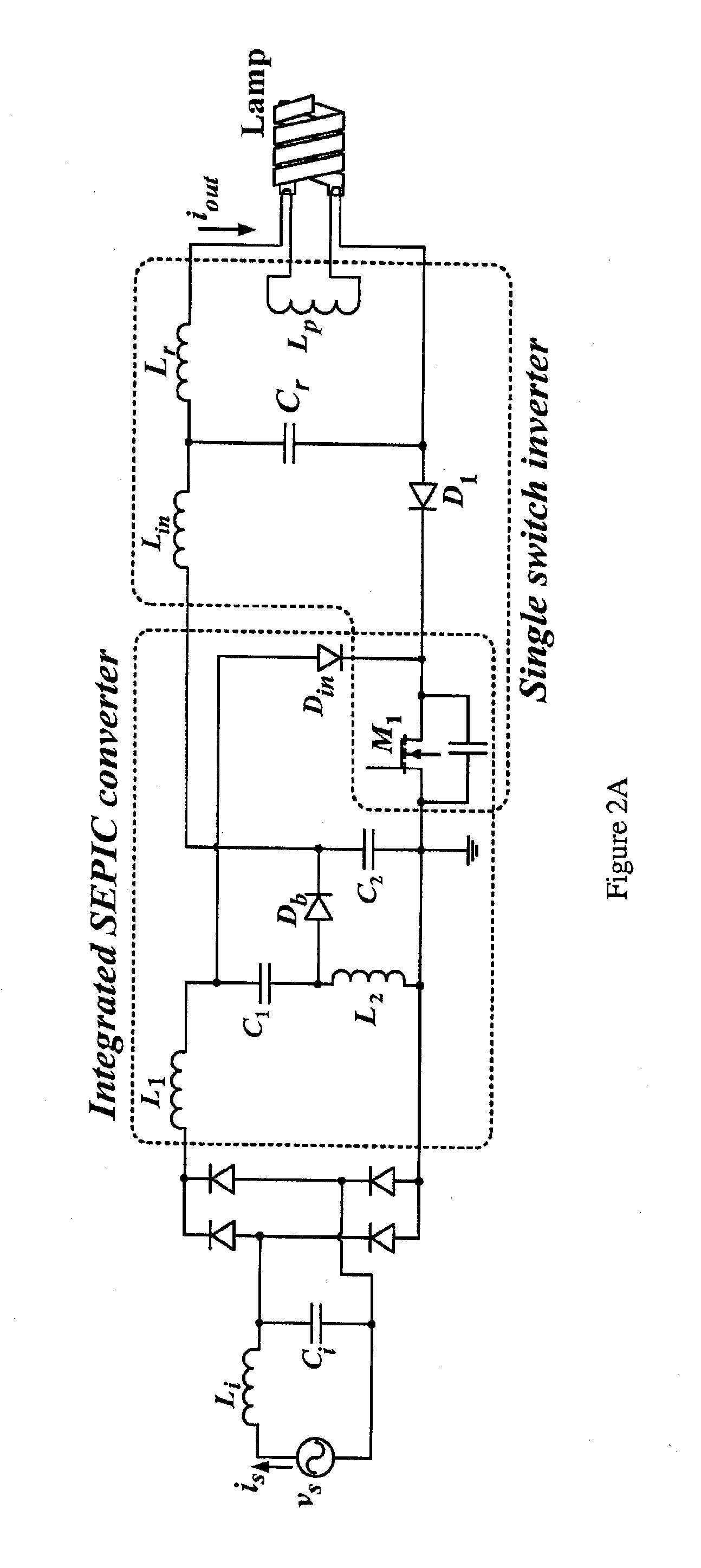
[0134]Performance of an electronic ballast circuit based on the embodiment of FIG. 2A was verified through simulation and an experimental prototype. A Sylvania Dulux® T / E 4-pin 26 W CFL with Iout=0.32 Arms was chosen as the testing load for the prototype with a line voltage of 110 Vrms 60 Hz. The switching frequency was 70 kHz and the quality factor was 2. The circuit parameters were calculated using the following steps:[0135](1): Rlamp was first calculated using Iout and Pout as shown in (14). Then the values of Lr, Cr and Lp were obtained using (3), (4) and (5) respectively.
Rlamp=PoutIout2=26W(0.32A)2≈250ΩLr=QRlamp2πfs=2(250Ω)2π(70kHz)=1.1mHCr=1(2πfs)2Lr=1(2π70kHz)2(1.1mH)=4.7nF(14)
Lp was selected to be higher than Lr so that sufficient high voltage would be guaranteed at the output during lamp ignition. In this example, Lp was selected to be 1.8 mH.[0136](2): Calculations of L1, L2, C2
[0137]The SEPIC inductors (L1 and L2) were calculated by (2) as fo...
PUM
 Abstract
Description
Claims
Application Information