Well Placement 3d Advisor- Method and System To Monitor And Assist A Well Placement Operation

a well placement and advisor technology, applied in the direction of drilling accessories, instruments, computing, etc., can solve the problems of difficult for operators to make good decisions, difficult to obtain an accurate view of what is going on during the drilling process, and inherently not indicating the future trajectory of the well

Inactive Publication Date: 2012-06-14
SCHLUMBERGER TECH CORP
View PDF4 Cites 21 Cited by
  • Summary
  • Abstract
  • Description
  • Claims
  • Application Information

AI Technical Summary

Problems solved by technology

Drilling operations used to drill oil and gas wells and the like face a number of challenges.
A particular problem arises because the drilling operation take place underground such that it is difficult to obtain an accurate view of what is going on during the drilling process.
It can therefore be difficult for the operator to be able to make good decisions to control the drilling process.
However, such measurements do not inherently indicate the future trajectory of the well.

Method used


Image

  • Well Placement 3d Advisor- Method and System To Monitor And Assist A Well Placement Operation
  • Well Placement 3d Advisor- Method and System To Monitor And Assist A Well Placement Operation
  • Well Placement 3d Advisor- Method and System To Monitor And Assist A Well Placement Operation

Examples


Embodiment Construction

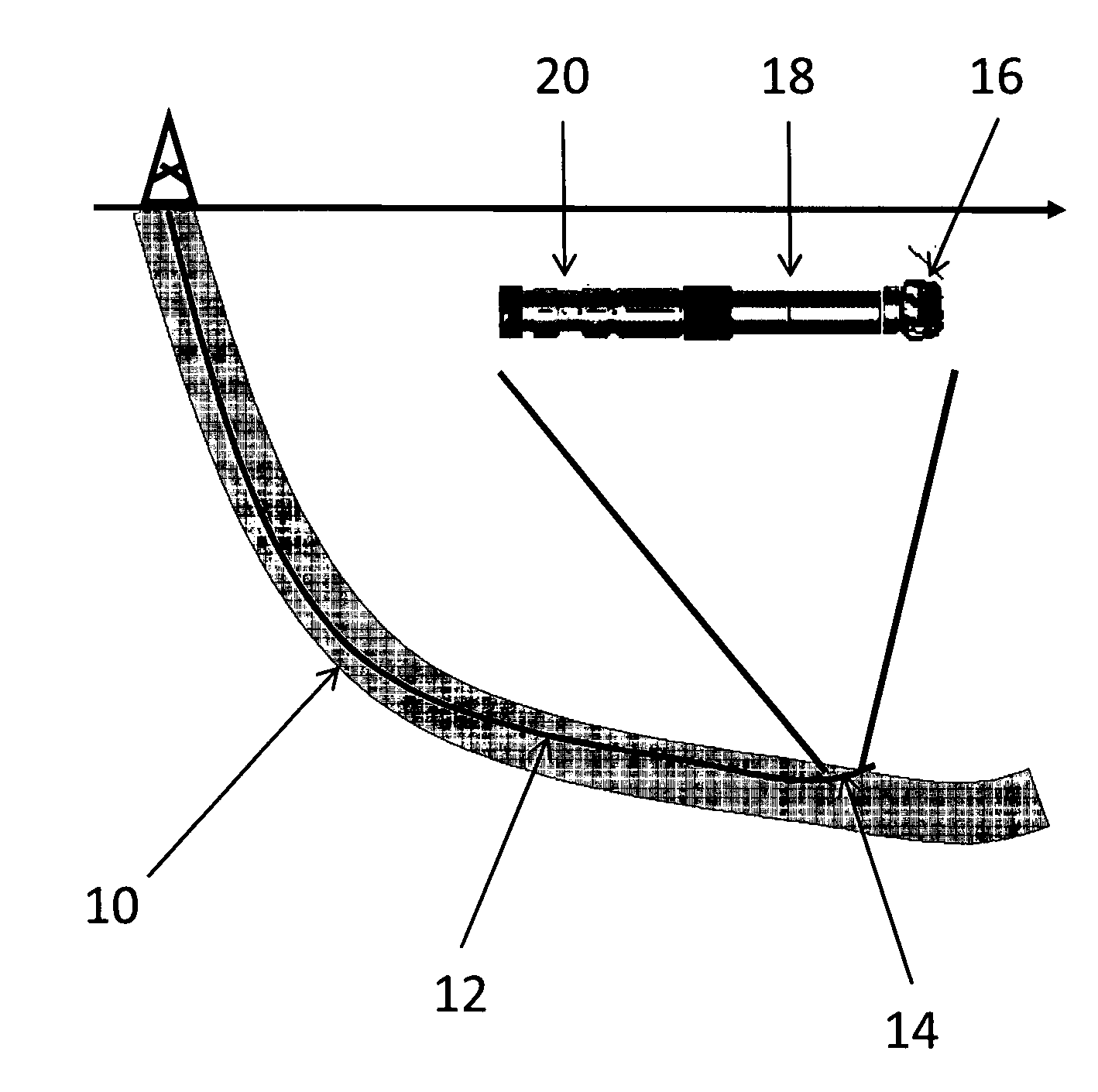
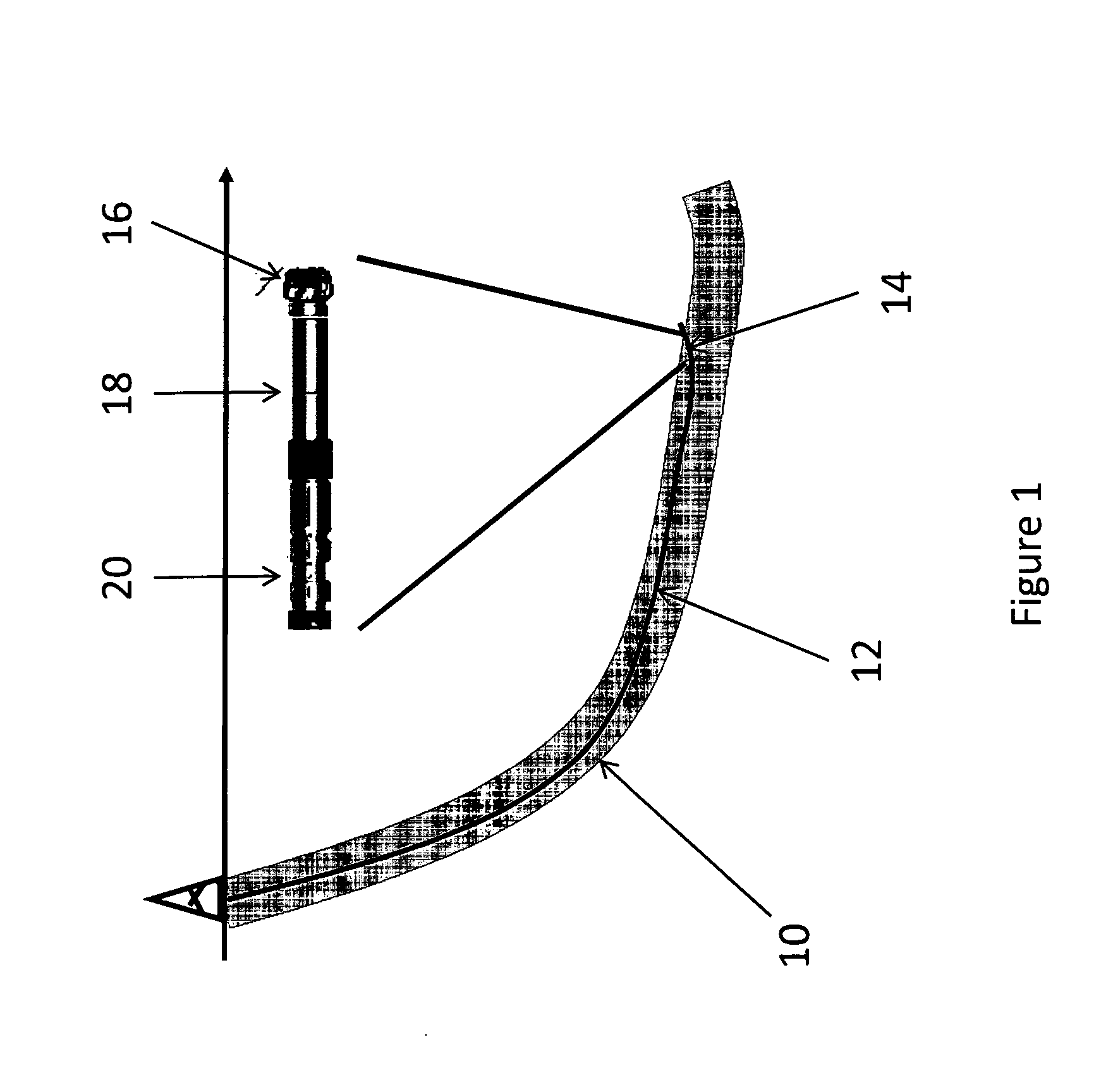
[0035]FIG. 1 shows schematically a well plan in two dimensions. The plan provides an intended trajectory 10 for the well to follow. This is typically larger than the well itself to provide a level of tolerance for deviation from the exact projected trajectory while still broadly following the intended path. As drilling progresses, more detailed information allows a more accurate estimate to be made of the well position 12 relative to the planned trajectory.

[0036]The drilling equipment (bottom hole assembly: BHA) 14 used to drill the well comprises a drill bit 16, a mud motor 18 and an electronics and logging while drilling (LWD) sub 20.

[0037]As can be see from FIG. 1, the BHA 14 is approaching the top of the planned trajectory. The driller now faces the challenge of modifying the drilling operation in order to keep the BHA 14 within the planned trajectory 10.

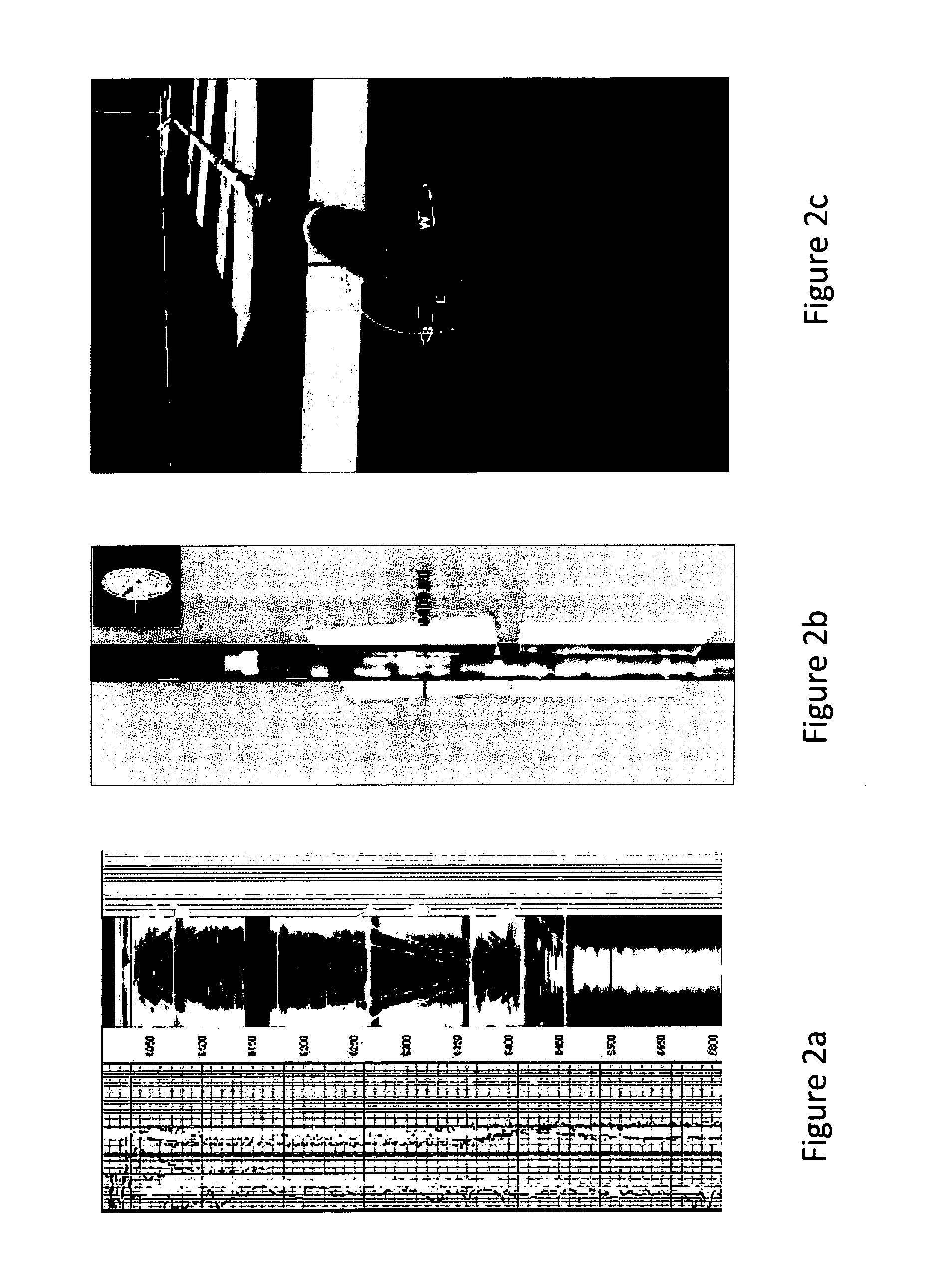
[0038]FIGS. 2a-2c show images of the various data available using Schlumberger's geoVISION tools and services and WellEye view...


PUM


Abstract

A method of displaying information relating to a well drilling operation, comprising generating a sub-surface model of the underground formation through which the well is being drilled; generating a representation of the well being drilled, of the drilling equipment being used to drill the well, including parameters relating to the use of the drilling equipment; generating a 3D image of the formation, the well and the drilling equipment; and generating an image within the 3D image comprising volumes representing virtual objects, such as a cone of possible well placement if drilling proceeds under the current conditions, or the envelope of investigation of a given sensor.

Description

TECHNICAL FIELD[0001]This invention relates to methods for displaying information relating to well drilling operations, of the type typically used in the oil and gas industry. In particular, the method provides images including an indication of possible outcomes ahead of the drill bit.BACKGROUND ART[0002]Drilling operations used to drill oil and gas wells and the like face a number of challenges. A particular problem arises because the drilling operation take place underground such that it is difficult to obtain an accurate view of what is going on during the drilling process. It can therefore be difficult for the operator to be able to make good decisions to control the drilling process.[0003]Drilling operations typically take place according to a drilling plan that is designed to place the well in the underground formations of interest. This plan will provide an intended well trajectory that the driller tries to follow. The plan will be based on sub-surface information obtained fr...

Claims


Application Information

Patent Timeline
Patent Type & Authority Applications(United States)
IPC IPC(8): G06T17/00
CPCE21B44/00G06T19/00G06T17/05
Inventor ROTHNEMER, PASCAL
Owner SCHLUMBERGER TECH CORP
Why Eureka
Try Eureka