Electronic equipment

a technology of electronic equipment and distance information, applied in the field of electronic equipment, can solve the problems of inability to detect the subject's distance information in principle, the inability to detect the distance information of a subject located within a non-common photographing range, and the inability to accurately detect the distance information

Inactive Publication Date: 2012-06-14
XACTI CORP
View PDF2 Cites 34 Cited by
  • Summary
  • Abstract
  • Description
  • Claims
  • Application Information

AI Technical Summary

Benefits of technology

[0010]Electronic equipment according to the present invention includes a distance information generating portion that generates distance information of a subject group. The distance information generating portion includes a first distance detecting portion that detects a distance of the subject group based on a plurality of input images obtained by simultaneously photographing the subject group from different visual points, a second distance detecting portion that detects a distance of the subject group by a detection method different from the detection method of the first distance detecting portion, and a combining portion that generates the distance information based on a detection result of the first distance detecting portion and a detection result of the second distance detecting portion.

Problems solved by technology

However, in the stereovision method, a subject distance of a subject located within a non-common photographing range cannot be detected in principle.
In other words, it is impossible to detected distance information of a subject existing only in one of the first and second images.
In addition, the distance information may not be detected accurately by the stereovision method for some subjects in a certain case.
The focused state adjustment by the digital focus cannot function appropriately for a region in which accuracy of the distance information is low.
A use of the distance information for the digital focus is described above, but the same problem occurs also in the case where the distance information is used for an application other than the digital focus.

Method used


Image

  • Electronic equipment
  • Electronic equipment
  • Electronic equipment

Examples


first embodiment

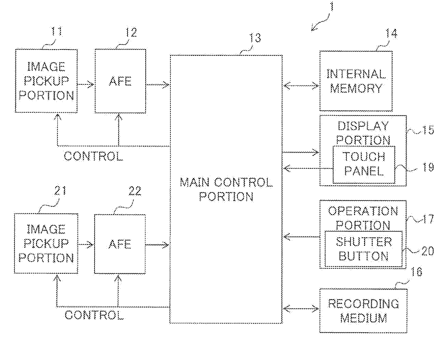
[0058]The first embodiment of the present invention will be described. In the first embodiment, as illustrated in FIG. 10, an image holding portion 54 is disposed in the detecting portion 52. The detecting portion 52 performs the second distance detecting process based on an input image sequence 400. Note that it is possible to consider that the image holding portion 54 is disposed outside the detecting portion 52. In addition, the image holding portion 54 may be disposed in the internal memory 14 illustrated in FIG. 1. The method of the second distance detecting process based on the input image sequence 400 described in the first embodiment is referred to as a detection method A1, for convenience sake. The combining portion 53 illustrated in FIG. 6 generates the output distance information by combining the first and second distance detection results by a combining method B1.

[0059]The input image sequence 400 indicates a set of a plurality of first input images arranged in time seri...

second embodiment

[0067]A second embodiment of the present invention will be described. A method of the second distance detecting process described in the second embodiment is referred to as a detection method A2. A method described in the second embodiment for generating the output distance information from the first and second distance detection results is referred to as a combining method B2.

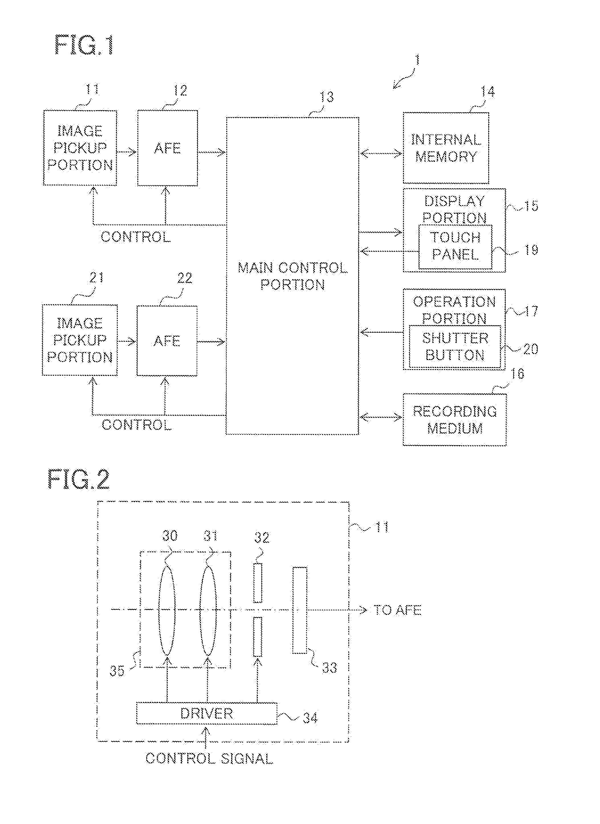
[0068]In the second embodiment, an image sensor 33A is used for each of the image sensor 33 of the image pickup portion 11 and the image sensor 33 of the image pickup portion 21. However, it is possible that only one of the image sensors 33 of the image pickup portions 11 and 21 is the image sensor 33A. The image sensor 33A is an image sensor that can realize so-called image plane phase difference AF.

[0069]As described above about the image sensor 33, the image sensor 33A is also constituted of a CCD, a CMOS image sensor, or the like. However, the image sensor 33A is provided with, in addition to third light r...

third embodiment

[0078]A third embodiment of the present invention will be described. A method of the second distance detecting process described in the third embodiment is referred to as a detection method A3. A method described in the third embodiment for generating the output distance information from the first and second distance detection results is referred to as a combining method B3.

[0079]In the third embodiment, the detecting portion 52 generates the second distance detection result from one input image 420 as illustrated in FIG. 12. The input image 420 is one first input image photographed by the image pickup portion 11 or one second input image photographed by the image pickup portion 21.

[0080]As a method for generating the second distance detection result (second range image) from one input image 420, a known arbitrary distance estimation method can be used. For instance, there are an available distance estimation method described in Non-patent document, Takano and other three persons, “...


PUM


Abstract

Electronic equipment is equipped with a distance information generating portion that generates distance information of a subject group. The distance information generating portion includes a first distance detecting portion that detects a distance of the subject group based on a plurality of input images obtained by simultaneously photographing the subject group from different visual points, a second distance detecting portion that detects a distance of the subject group by a detection method different from the detection method of the first distance detecting portion, and a combining portion that generates the distance information based on a detection result of the first distance detecting portion and a detection-result of the second distance detecting portion.

Description

CROSS-REFERENCE TO RELATED APPLICATIONS[0001]This nonprovisional application claims priority under 35 U.S.C. §119(a) on Patent Application No. 2010-275593 filed in Japan on Dec. 10, 2010, the entire contents of which are hereby incorporated by reference.BACKGROUND OF THE INVENTION[0002]1. Field of the Invention[0003]The present invention relates to electronic equipment such as an image pickup apparatus or a personal computer.[0004]2. Description of Related Art[0005]There is proposed a function of adjusting a focused state of a photographed image by image processing, and a type of processing for realizing this function is also called digital focus. In order to perform the digital focus, distance information of a subject in the photographed image is necessary.[0006]As a general method of obtaining the distance information, there is a stereovision method using a two-eye camera. In the stereovision method, first and second images are photographed simultaneously using first and second ca...

Claims


Application Information

Patent Timeline
Patent Type & Authority Applications(United States)
IPC IPC(8): H04N13/02H04N13/239
CPCG01C3/085H04N13/0239H04N5/23212H04N13/239H04N23/672H04N23/673H04N25/704
Inventor KOJIMA, KAZUHIROFUKUMOTO, SHINPEI
Owner XACTI CORP
Why Eureka
Try Eureka