Image Display Apparatus and Image Sensing Apparatus

a technology of image display and image sensing, which is applied in the direction of color television details, television system details, television systems, etc., can solve the problems of increasing the time required for taking an image, user misunderstanding the region that is actually in focus, and difficulty in understanding which parts of the af area are in focus

Inactive Publication Date: 2010-06-24
SANYO ELECTRIC CO LTD
View PDF1 Cites 49 Cited by
  • Summary
  • Abstract
  • Description
  • Claims
  • Application Information

AI Technical Summary

Benefits of technology

[0013]Alternatively and specifically, for example, the subject distance detection portion extracts a predetermined high frequency component contained in each of a plurality of color signals representing the

Problems solved by technology

However, in this method, it is difficult to understand which part in the AF area is in focus because the display screen of the image sensing apparatus is small.
Therefore, a user may misunderstand the region that is actually in focus.
However, this conventional method requires multi-step movement of the focus lens, so

Method used


Image

  • Image Display Apparatus and Image Sensing Apparatus
  • Image Display Apparatus and Image Sensing Apparatus
  • Image Display Apparatus and Image Sensing Apparatus

Examples


first embodiment

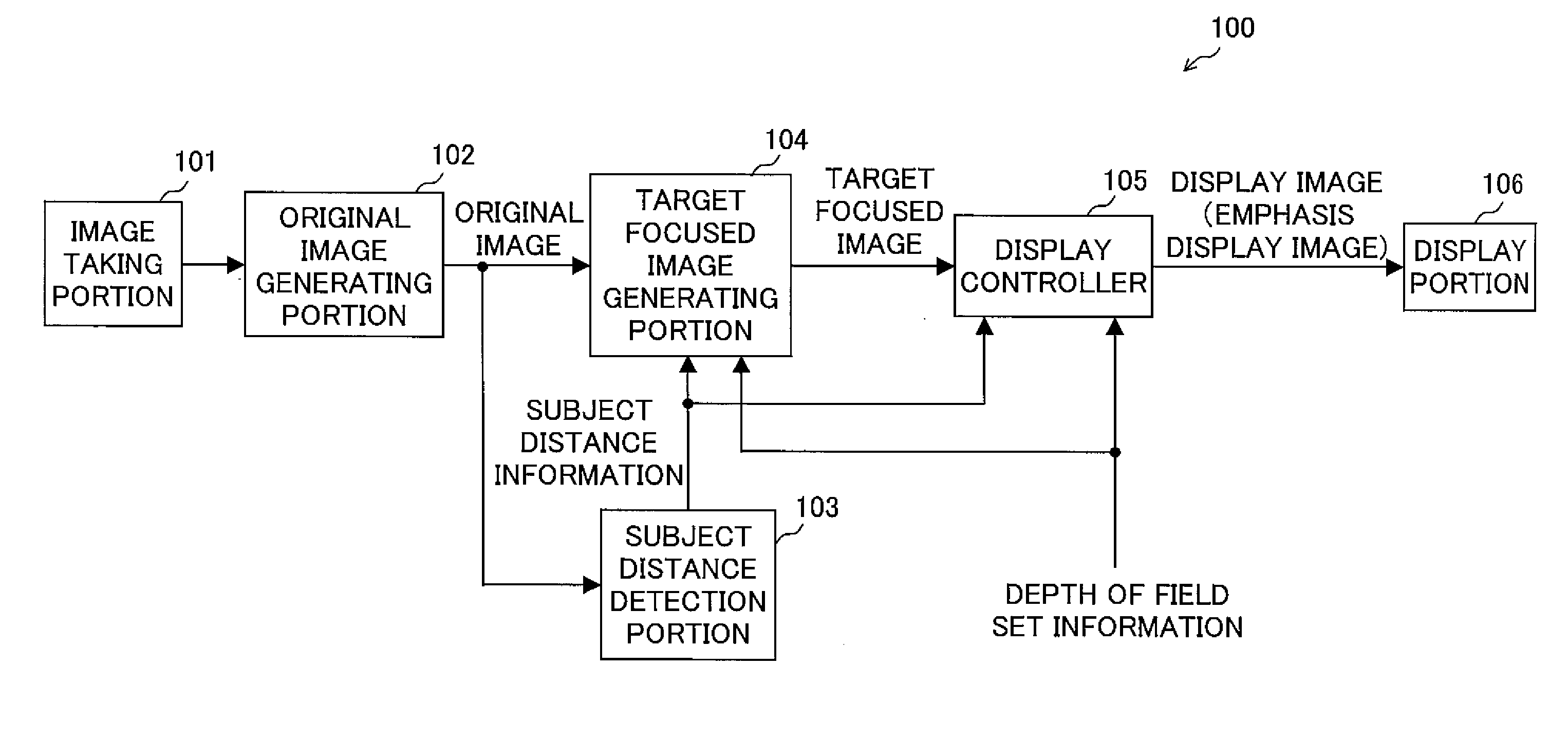
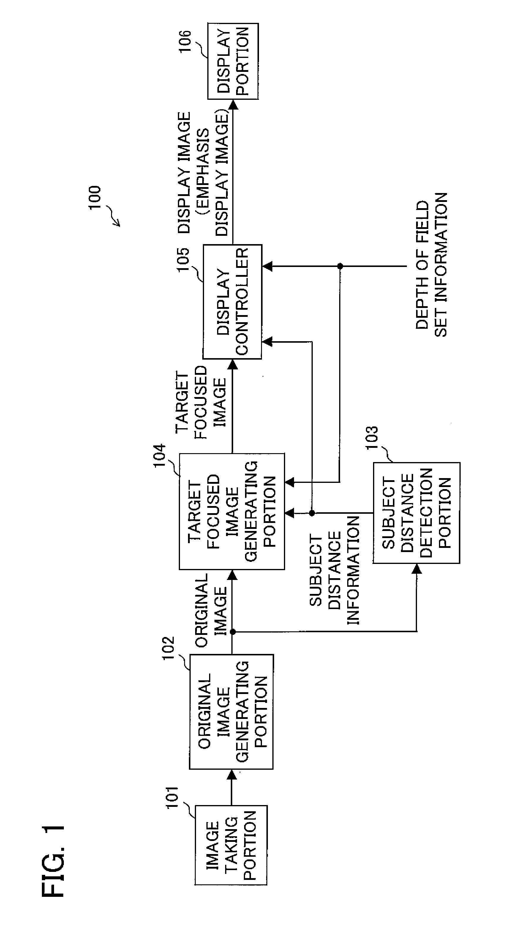
[0046]First, a first embodiment of the present invention will be described. FIG. 1 is a schematic general block diagram of an image sensing apparatus 100 according to a first embodiment. The image sensing apparatus 100 (and other image sensing apparatuses of other embodiments that will be described later) is a digital still camera that can take and record still images or a digital video camera that can take and record still images and moving images. The image sensing apparatus 100 includes individual portions denoted by numerals 101 to 106. Note that “image taking” and “image sensing” have the same meaning in this specification.

[0047]The image taking portion 101 includes an optical system and an image sensor such as a charge coupled device (CCD), and delivers an electric signal representing an image of a subject when a image is taken with the image sensor. The original image generating portion 102 generates image data by performing predetermined image signal processing on an output ...

second embodiment

[0069]A second embodiment of the present invention will be described. In the second embodiment, the method of generating the target focused image from the original image will be described in detail, and a detailed structure and an operational example of the image sensing apparatus according to the present invention will be described.

[0070]With reference to FIGS. 6, 7A to 7C and 8, characteristics of a lens 10L that are used in the image sensing apparatus of the second embodiment will be described. The lens 10L has a predetermined axial chromatic aberration that is relatively large. Therefore, as illustrated in FIG. 6, a light beam 301 directed from a point light source 300 to the lens 10L is separated by the lens 10L into a blue color light beam 301B, a green color light beam 301G and a red color light beam 301R. The blue color light beam 301B, the green color light beam 301G and the red color light beam 301R form images at different image formation points 302B, 302G and 302R. The b...


PUM


Abstract

An image display apparatus includes a subject distance detection portion which detects a subject distance of each subject whose image is taken by an image taking portion, an output image generating portion which generates an image in which a subject positioned within a specific distance range is in focus as an output image from an input image taken by the image taking portion, and a display controller which extracts an in-focus region that is an image region in the output image in which region the subject positioned within the specific distance range appears based on a result of the detection by the subject distance detection portion, and controls a display portion to display a display image based on the output image so that the in-focus region can be visually distinguished.

Description

CROSS-REFERENCE TO RELATED APPLICATIONS[0001]This nonprovisional application claims priority under 35 U.S.C. §119(a) on Patent Application No. 2008-322221 filed in Japan on Dec. 18, 2008, the entire contents of which are hereby incorporated by reference.BACKGROUND OF THE INVENTION[0002]1. Field of the Invention[0003]The present invention relates to an image display apparatus which display an image based on a taken image and an image sensing apparatus including the image display apparatus.[0004]2. Description of Related Art[0005]In an image sensing apparatus such as a digital camera having an automatic focus function, automatic focus control is usually performed optically so that a subject within an automatic focus (AF) area becomes in focus, and after that an actual shooting process is performed. A result of the automatic focus control can be checked in many cases on a display screen provided to the image sensing apparatus. However, in this method, it is difficult to understand whic...

Claims


Application Information

Patent Timeline
IPC IPC(8): H04N5/222
CPCH04N5/23293H04N5/23212H04N23/675H04N23/63
Inventor TAKAYANAGI, WATARUOKU, TOMOKO
Owner SANYO ELECTRIC CO LTD
Why Eureka
Try Eureka