Programming reversible resistance switching elements

a technology of resistance switching element and programming method, which is applied in the field of data storage technology, can solve the problems of difficult programming of memory cells, difficult operation of memory devices that employ reversible resistance switching materials, and difficulty in efficiently programming all memory cells using the same programming conditions, etc., and achieves the effect of reducing worst case current and/or power consumption, saving time and/or power, and high programming bandwidth

Active Publication Date: 2012-06-14
SANDISK TECH LLC
View PDF4 Cites 101 Cited by
  • Summary
  • Abstract
  • Description
  • Claims
  • Application Information

AI Technical Summary

Benefits of technology

[0008]A storage system and method for operating the storage system that uses reversible resistance-switching elements is described. Techniques are disclosed herein for varying programming conditions to account for different resistances that memory cells have. These techniques can program memory cells in fewer attempts, which can save time and / or power. Techniques are disclosed herein for achieving a high programming bandwidth while reducing the worst case current and / or power consumption. In one embodiment, a page mapping scheme is used to program multiple memory cells in parallel in a way that reduces the worst case current and / or power consumption.
[0011]One embodiment is a method of operating non-volatile storage that includes groups of reversible resistance-switching elements. The current and / or power used by a group when programming a selected reversible resistance-switching element in the group is a function of the location of the selected reversible resistance-switching element in its group. The method comprises the following. A unit of data to be stored in the non-volatile storage is received. The unit of data is mapped to reversible resistance-switching elements in different groups based on the location of the reversible resistance-switching elements in order to minimize the worst case current and / or power consumption when programming the unit of data in parallel into reversible resistance-switching elements in different groups. Reversible resistance-switching elements in different groups are programmed in parallel based on the mapping.

Problems solved by technology

However, operating memory devices that employ reversible resistance-switching materials is difficult.
Specifically, programming the memory cells can be challenging.
Therefore, it can be difficult to efficiently program all of the memory cells using the same programming conditions.
However, it can be difficult to achieve a high programming bandwidth while staying within a maximum current and / or power consumption of the memory device.

Method used


Image

  • Programming reversible resistance switching elements
  • Programming reversible resistance switching elements
  • Programming reversible resistance switching elements

Examples


Embodiment Construction

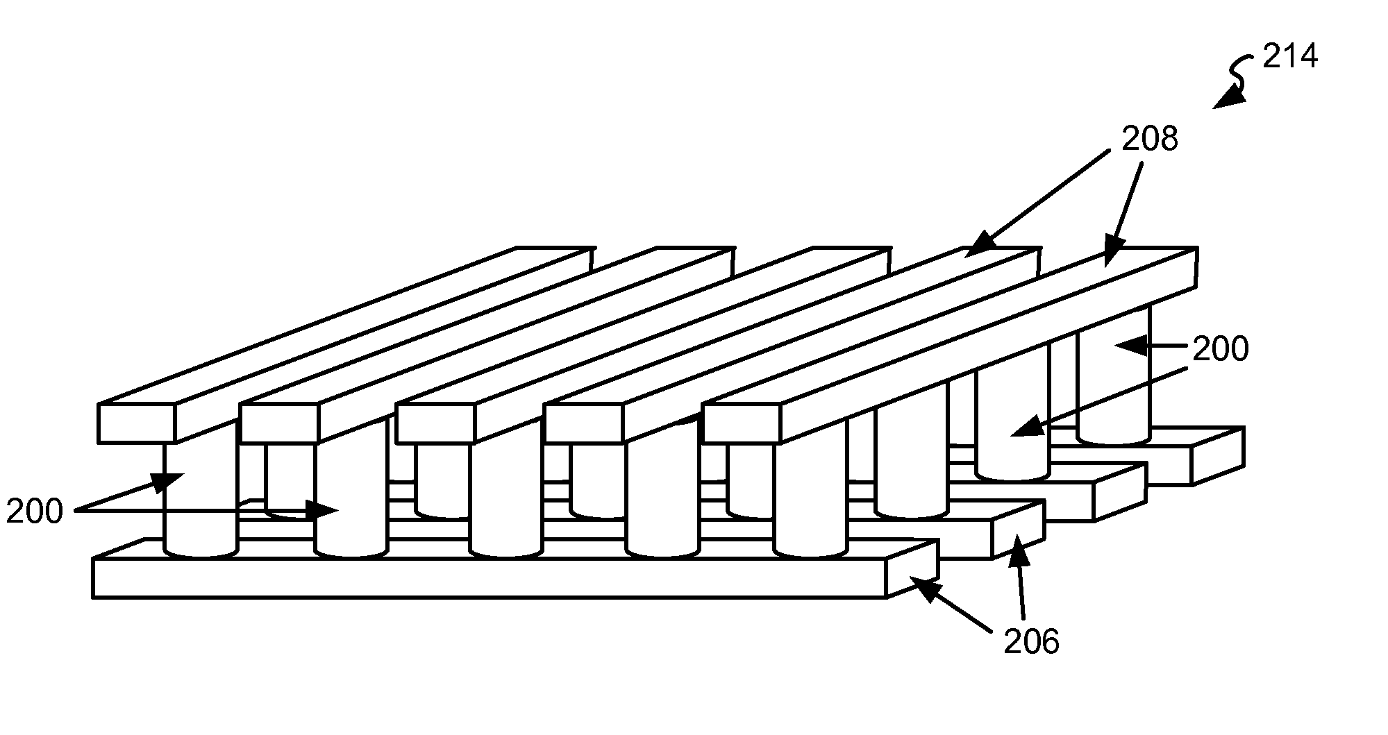
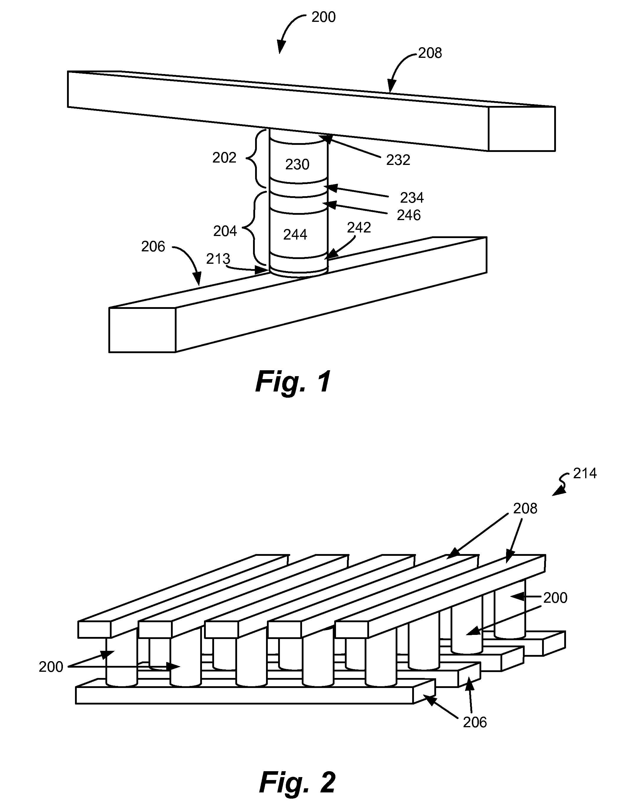
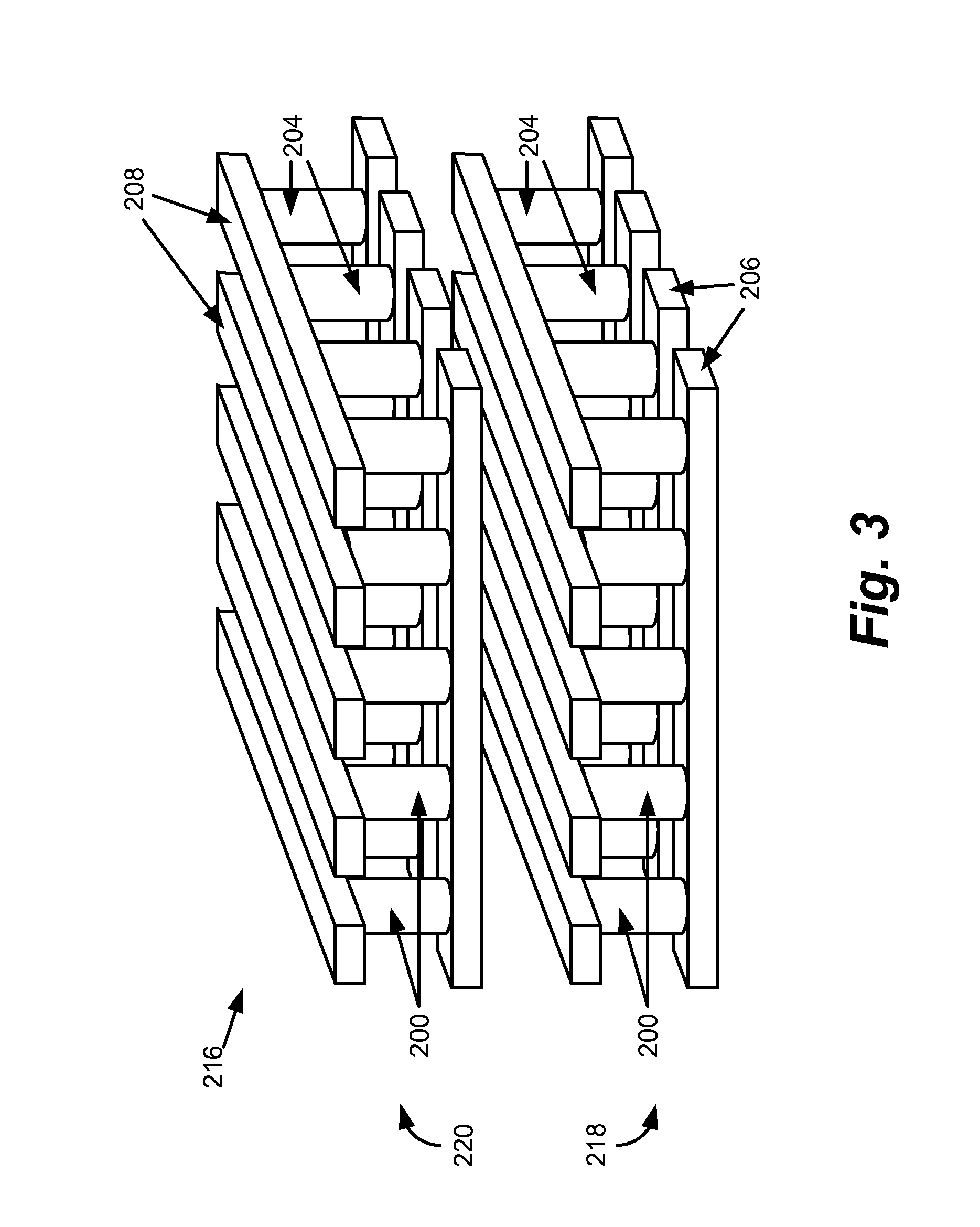
[0029]A memory system is provided that includes memory cells that have a reversible resistivity-switching element. Various systems and methods are disclosed for varying the programming conditions to account for different resistances that reversible resistivity-switching elements have. For example, the resistance of the reversible resistivity-switching element in the memory cell being programmed may be used to determine a suitable programming voltage in order to reduce the number of times that programming the memory cell must be attempted before it RESETS (or SETS). Various systems and methods are disclosed herein for achieving a high programming bandwidth while reducing the worst case current and / or power consumption. For example, the power that is consumed by an entire group of memory cells (e.g., block) when programming a selected memory cell within the group may be a function of the location of the selected memory cell within the group. In one embodiment, a page mapping scheme is...


PUM


Abstract

A storage system and method for operating the storage system that uses reversible resistance-switching elements is described. Techniques are disclosed herein for varying programming conditions to account for different resistances that memory cells have. These techniques can program memory cells in fewer attempts, which can save time and / or power. Techniques are disclosed herein for achieving a high programming bandwidth while reducing the worst case current and / or power consumption.

Description

CLAIM OF PRIORITY[0001]This application is a divisional application of U.S. patent application Ser. No. 12 / 488,159, entitled “PROGRAMMING REVERSIBLE RESISTANCE SWITCHING ELEMENTS,” filed Jun. 19, 2009, which is incorporated herein by reference in its entirety.BACKGROUND[0002]The present invention relates to technology for data storage.Description of the Related Art[0003]A variety of materials show reversible resistance-switching behavior. These materials include chalcogenides, carbon polymers, perovskites, and certain metal oxides and nitrides. Specifically, there are metal oxides and nitrides which include only one metal and exhibit reliable resistance switching behavior. This group includes, for example, NiO, Nb2O5, TiO2, HfO2, Al2O3, MgOx, CrO2, VO, BN, and AlN, as described by Pagnia and Sotnick in “Bistable Switching in Electroformed Metal-Insulator-Metal Device,” Phys. Stat. Sol. (A) 108, 11-65 (1988). A layer of one of these materials may be formed in an initial state, for ex...

Claims


Application Information

Patent Timeline
Patent Type & Authority Applications(United States)
IPC IPC(8): G11C11/00
CPCG11C7/00G11C8/12G11C13/0007G11C13/0064G11C13/0069G11C2213/72G11C2013/0088G11C2013/009G11C2213/32G11C2213/34G11C2013/0076G11C13/0033G11C13/00G11C16/12
Inventor SEKAR, DEEPAK C.SCHUEGRAF, KLAUSSCHEUERLEIN, ROY
Owner SANDISK TECH LLC
Why Eureka
Try Eureka