Developer cartridge with counting mechanism

a technology of developer cartridges and counting mechanisms, which is applied in the direction of electrographic process apparatus, instruments, optics, etc., can solve the problems of difficult control of the production process and corresponding increase in the production cost of the developer cartridge, and achieve the effect of simple and convenient and reliable counting mechanism, high matching precision, and high precision requirements

Active Publication Date: 2012-06-14
NINESTAR CORP
View PDF2 Cites 20 Cited by
  • Summary
  • Abstract
  • Description
  • Claims
  • Application Information

AI Technical Summary

Benefits of technology

[0030]Due to adoption of the technical proposal, the counting mechanism driving member drives the protrusions to move in the direction perpendicular to the side wall of the cartridge body, and the first position and the second position are positioned in different positions at different distance from the side wall of the cartridge body, thus the problems of, not only guaranteeing that the moving member does not rotate around the rotary shaft when in contact with the contact lever but also guaranteeing that the high matching precision requirement on driving the information detection mechanism to rotate is met, in the prior art do not occur. Therefore, the invention solves the problems of difficult production, high precision requirement, etc. in the prior art. The working principle of the technical proposal adopted by the invention is greatly different from that in the prior art. Therefore, the invention has the advantages of making the structure of the counting mechanism of the developer cartridge simpler and more convenient and reliable, reducing the production precision and production cost, and improving the market competitiveness of the developer cartridge.

Problems solved by technology

Therefore, for solving the problem of how to guarantee that the moving member does not rotate around the rotary shaft when in contact with the contact lever but the information detection mechanism is driven to rotate and that the moving member rotates around the rotary shaft when in contact with the blocking protrusion, higher matching precision requirement between the moving member and the rotary shaft is required to meet, thus the production process is difficult to control and the production cost of the developer cartridge is correspondingly increased.

Method used


Image

  • Developer cartridge with counting mechanism
  • Developer cartridge with counting mechanism
  • Developer cartridge with counting mechanism

Examples


embodiment 1

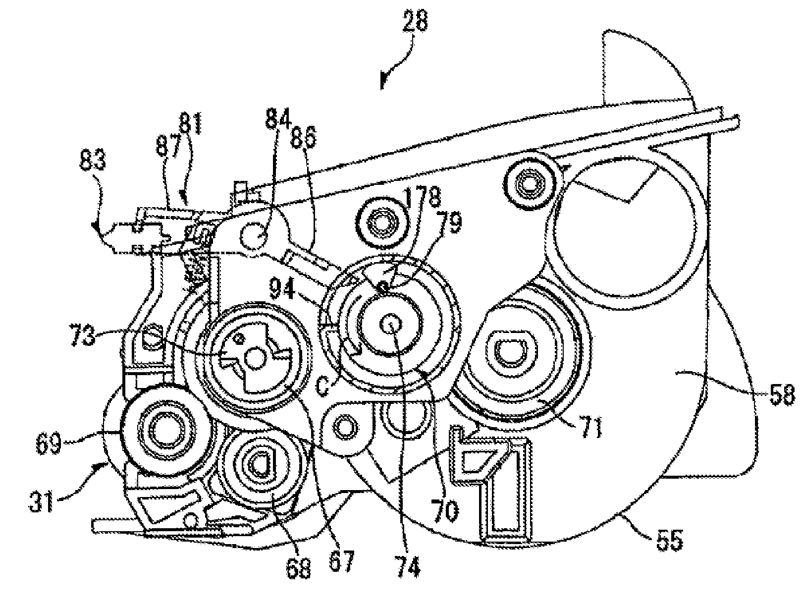
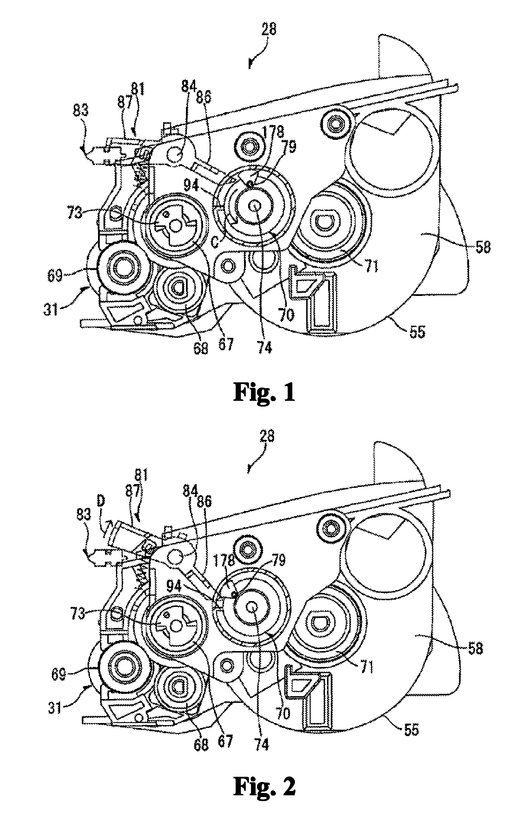
[0045]Unless otherwise specified, the developer cartridge of the embodiment has the same structure with the developer cartridge shown in FIG. 1.

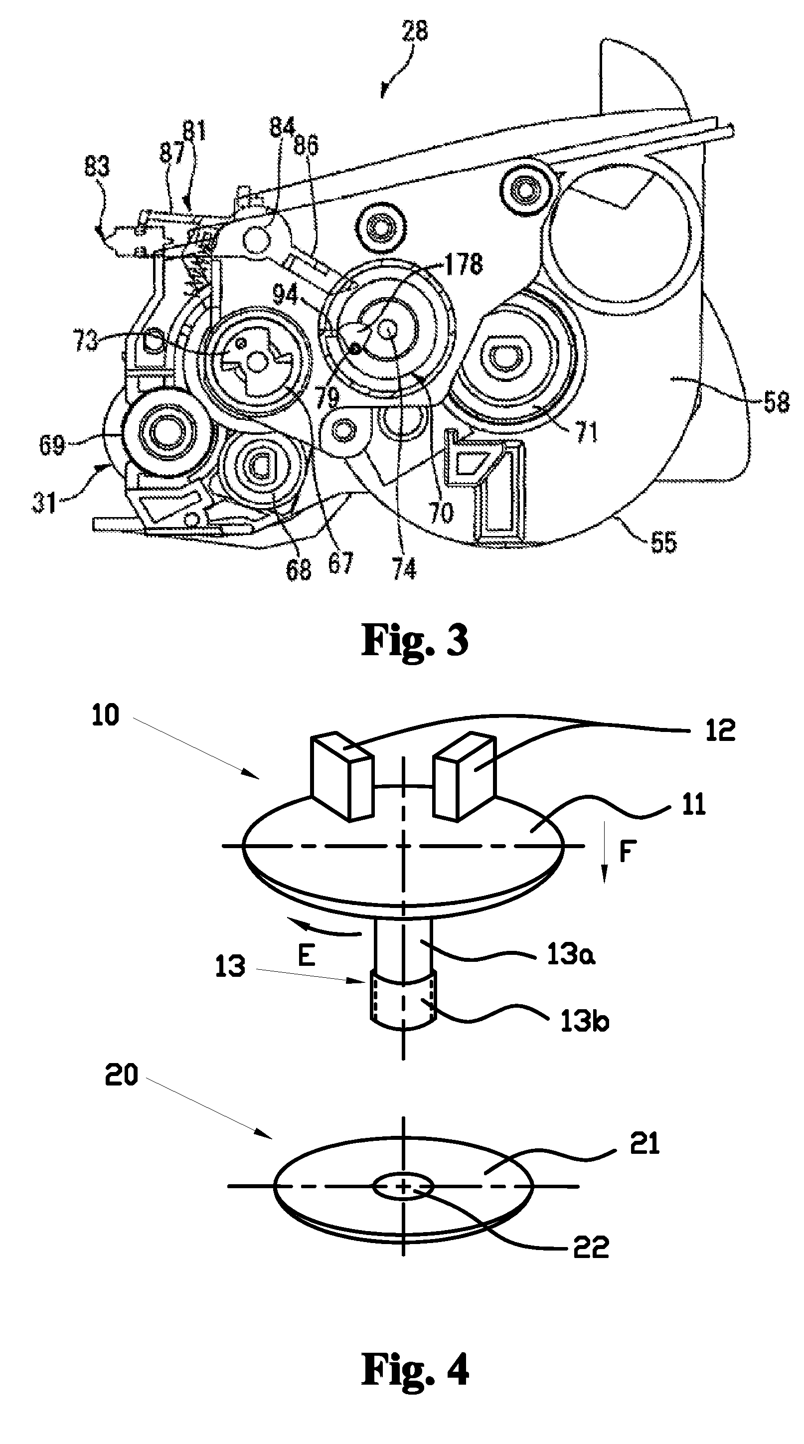
[0046]FIG. 4 is a structure diagram of a counting mechanism in the embodiment 1. The counting mechanism comprises a rotary member 10 and a fixed member 20, wherein the rotary member 10 is provided with a hanging wall 11, protrusions 12 and a cylinder 13; the cylinder 13 comprises an unthreaded portion 13a and a threaded portion 13b; the fixed member 20 comprises a footwall 21 and a screwed hole 22 corresponding to the threaded portion 13b, is fixed on the side wall 58 of the toner hopper 55 of the developer cartridge as shown in FIG. 1, and is motionless relative to the toner hopper 55; and a gear (not shown in the figure) is arranged on the outer circumference of the hanging wall 11 of the rotary member 10 and engaged with the input gear 67, and receives power from the input gear 67 to drive the rotary member 10 to rotate around a central s...

embodiment 2

[0056]The FIGS. 7 and 8 illustrate the embodiment 2. Unless otherwise specified, the developer cartridge of the embodiment has the same structure with the developer cartridge of the embodiment 1.

[0057]The counting mechanism of the embodiment comprises a rotary member 10a and a fixed member 20a, wherein the rotary member 10a is provided with a hanging wall 14, protrusions 15 and a screwed hole 16; a footwall 23 and a cylinder 24 are arranged on the fixed member 20a; the cylinder 24 comprises a threaded portion 24a and an unthreaded portion 24b; a gear is arranged on the outer circumference of the hanging wall 14 of the rotary member 10a and engaged with the input gear 67; and the fixed member 20a is arranged on the side wall 58 of the toner hopper 55 and is motionless relative to the toner hopper 55.

[0058]FIG. 7 is a schematic diagram of the counting mechanism of the embodiment on the initial state. Herein the protrusions 15 on the rotary member 10a are extended out of the side wall ...

embodiment 3

[0061]Unless otherwise specified, the developer cartridge of the embodiment has the same structure with the developer cartridge shown in FIG. 1.

[0062]As illustrated in FIG. 9, the counting mechanism of the embodiment comprises a rotary member 10b and a fixed member 20b, wherein the rotary member 10b comprises a hanging wall 17, protrusions 18 and a support pillar 19; the fixed member 20b comprises a footwall 25 and an opening 26, is fixed on the side wall 58 of the toner hopper 55, and is motionless relative to the developer cartridge 28; a gear is arranged on the outer circumference of the hanging wall 17 of the rotary member 10b and engaged with the input gear 67 of the developer cartridge; and the rotary member 10b can rotate clockwise around the center of the hanging wall 17 (along the G direction as shown in FIG. 9).

[0063]FIGS. 9 and 10 are schematic diagrams of the counting mechanism of the embodiment on the initial state. When the counting mechanism is on the state, the protr...


PUM


Abstract

The invention provides a developer cartridge with a counting mechanism. The developer cartridge comprises a developer and the counting mechanism, wherein the counting mechanism is provided with protrusions which come in contact with a contact lever on an electronic photographing device so as to count the developer cartridge; and each protrusion has a first position and a second position in the direction perpendicular to a side wall of the developer cartridge, and is, in the first position, in contact with the contact lever, but is not, in the second position, in contact with the contact lever. The working principle of the developer cartridge adopting the counting mechanism is greatly different from the prior art. Therefore, the structure of the counting mechanism of the developer cartridge is simpler and more convenient and reliable; the production precision and the production cost are reduced; and the market competitiveness of the developer cartridge is improved.

Description

FIELD OF THE INVENTION[0001]The invention relates to a developer cartridge with a counting mechanism.BACKGROUND OF THE INVENTION[0002]The invention relates to a developer cartridge which can be detachably mounted on an electronic photographing device such as a laser printer, a duplicating machine and a facsimile machine, wherein a counting mechanism is arranged on the developer cartridge and can be used with a detector on the electronic photographing device to give instruction of whether the developer cartridge is a new developer cartridge to the electronic photographing device which can then restart calculating the service life of the developer cartridge.[0003]As illustrated in FIGS. 1, 2 and 3, the invention relates to a developer cartridge in the prior art, wherein the developer cartridge adopts a conventional counting mechanism.[0004]A toner hopper 55, a developing component 31, a toner feeding component (not shown), a stirring component (not shown) and a developer (not shown) a...

Claims


Application Information

Patent Timeline
Patent Type & Authority Applications(United States)
IPC IPC(8): G03G15/06
CPCG03G15/0896G03G15/55G03G15/553
Inventor PENG, QINGFEICAO, JIANXIN
Owner NINESTAR CORP
Why Eureka
Try Eureka