Self-deploying floodwall

a floodwall and self-deploying technology, applied in the field of floodwalls, can solve the problems of increasing the frequency of coastal flooding, long response time, and limited application of temporary flood protection structures, and achieve the effect of improving the design and functionality of conventional cantilever floodwalls

Inactive Publication Date: 2012-06-14
EFTEKHARZADEH SHAHRIAR
View PDF15 Cites 31 Cited by
  • Summary
  • Abstract
  • Description
  • Claims
  • Application Information

AI Technical Summary

Benefits of technology

[0005]The present invention provides an answer to the above stated need with a new type of cantilever floodwall, which improves the design and functionality of conventional cantilever floodwalls while fully complying with their engineering principles as described in the US Army Corp of Engineers Engineering Manual EM 1110-2-2502 dated 29 Sep. 1989. The differentiating feature of the present invention is that it replaces the fixed stem of conventional cantilever floodwalls with a stem that lays down flat at or belowground during normal non-flood times such that it does not create any physical and visual obstructions above ground. This makes the present invention feasible in areas where a permanent aboveground floodwall would be infeasible and unacceptable for a whole host of reasons. The stem of the present invention self-deploys to the vertical upright position, solely by the action of the floodwaters by gradually rotating and rising up in the direction of the intruding floodwaters towards the vertical position, while simultaneously providing flood protection as it rises to its maximum design height in the full vertical position.
[0006]The above-described feature of the present invention is realized by the stem of the present invention being constructed to be buoyant such that it floats in water, and pivoted at ground level having freedom of rotation from the horizontal ground level on the water side up to the vertical position and back down. The stem is comprised of individual segments longitudinally, with each segment counterbalanced about a cylindrical pivot at ground level in a seesaw configuration. Individual concrete compartments belowground house the counterbalancing portion of each stem segment. The cylindrical pivots of each stem segment are mounted on a watertight seat on the upper waterside corner of each compartment, with the aboveground portion of the stem segment extending out above ground. Adjacent stem segments are separated by a small gap, and are attached to one another with elastic sheet material, which gives the stem longitudinal flexibility and seals the gap between the segments.
[0007]The stem normally resides in the rotated down position within a porous pre-excavated shallow trench, with a small depth of native soil or other cover over it. During flood, water enters the trench at a certain design elevation imposing uplift and momentum force on the stem. This forces the stem to rotate up towards the vertical deployed position, while simultaneously providing flood protection as it rises. Spring-loaded dampeners inside each concrete compartment, in-between the counterbalancing portion of each segment and the waterside wall of the concrete compartment, transfer the forces upon the stem to the concrete compartment, restrict the rotational speed of the stem, dampen stem oscillations, and prevent slamming The waterside wall of the concrete compartments provides the reaction for the forces imposed by floodwaters on the aboveground portion of the stem via the spring-loaded dampeners when the stem is in partially raised position, and by direct contact when the stem is in the fully deployed vertical position. The stem body is constructed from structural materials to safely withstand the maximum bending moment and shear forces, which occur at the pivot. The stem may be designed to automatically rotate back to the down position with receding water or remain locked in place as it rises for maintenance after a flood event before manually being brought down.
[0008]The above-described functionality of the present invention, in which the stem resides belowground during normal times and self-deploys upon start of flooding, removes the physical and visual obstruction of conventional floodwalls, making the present invention feasible in flat coastal regions and flood-prone areas along and in river floodplains.
[0009]It is an object of this invention to provide a water-activated and self-deploying permanent floodwall system that can protect against intruding seawater and floodwaters without creating a physical and visual obstruction to and from the waterfront during normal times.
[0010]It is an object of this invention to provide improved elements and arrangements by apparatus for the purposes described thereof, which is comparable in cost with existing systems, dependable, and fully effective in accomplishing its intended purposes.

Problems solved by technology

Sea level rise due to global warming is increasing the frequency of coastal flooding, particularly in low lying and flat beach areas.
Permanent flood protection structures create a physical and visual obstruction to and from the waterfront, which makes them infeasible in populated low lying and flat beach areas where flood protection is most needed.
Temporary flood protection structures have limited application, long response time, and entail significant effort and cost for deployment.

Method used


Image

  • Self-deploying floodwall
  • Self-deploying floodwall
  • Self-deploying floodwall

Examples


Embodiment Construction

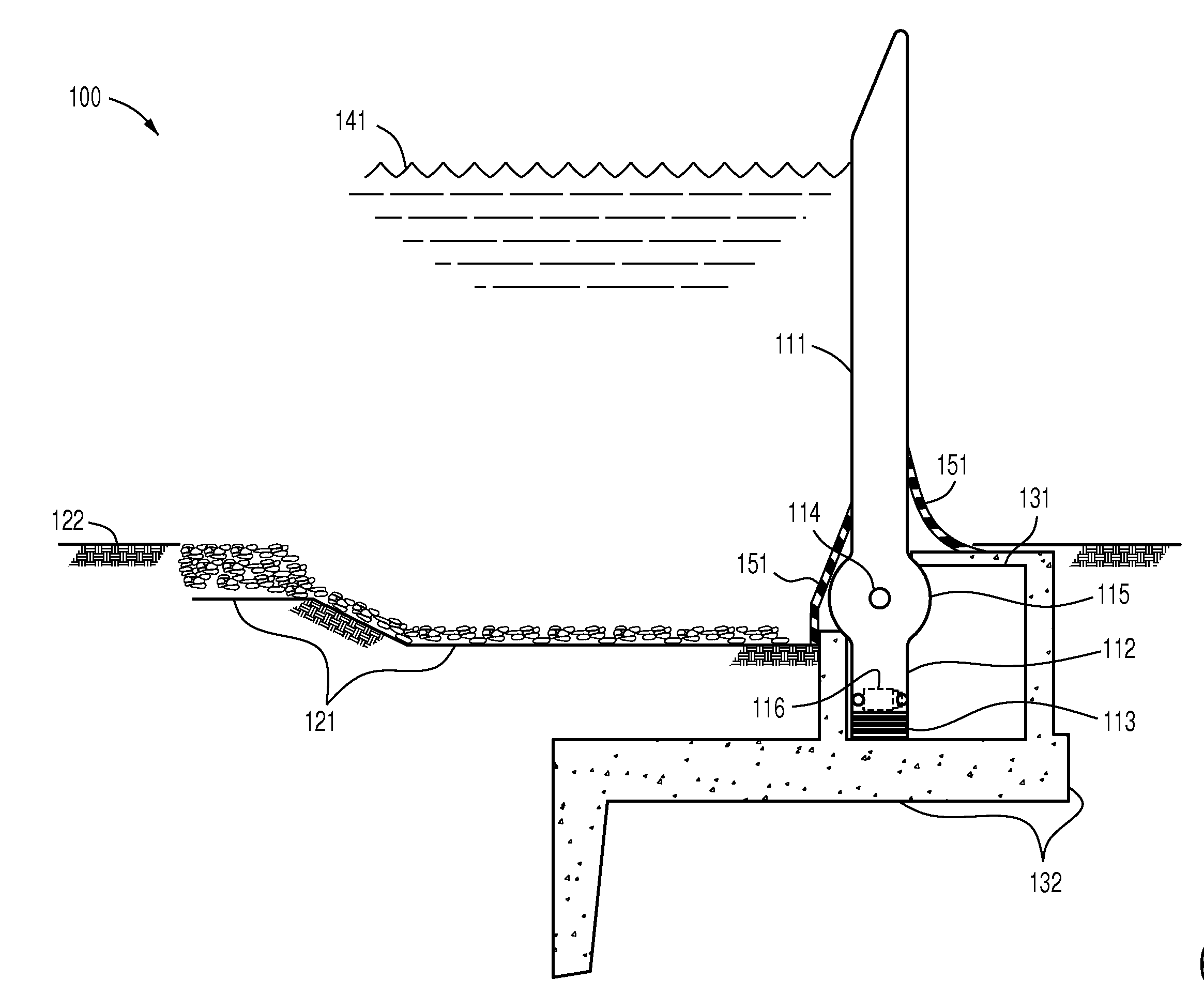
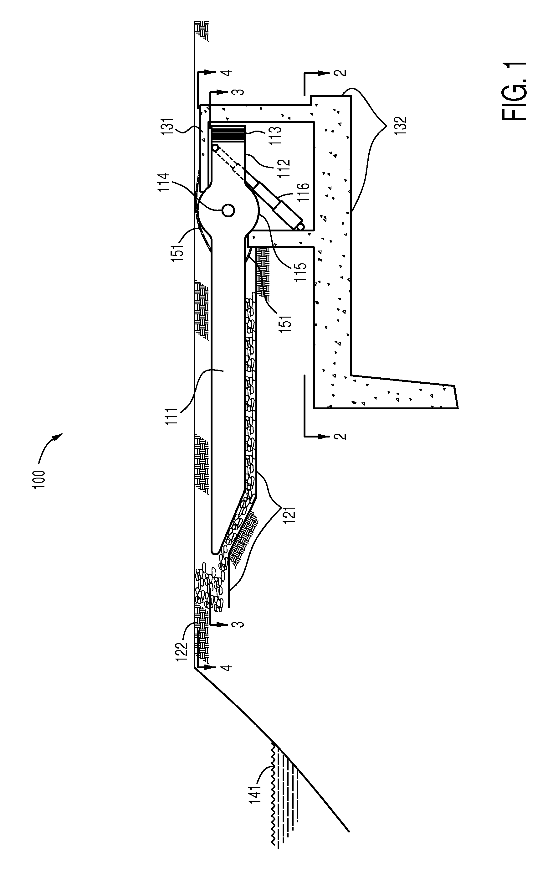
[0019]Referring first to FIG. 1, there is shown the preferred embodiment of the invention in the form of self-deploying floodwall apparatus 100 that is constructed onshore as a permanent structure at a predetermined distance away from flood prone waters 141. The apparatus comprised of longitudinally connected stem segments 111 that are buoyant and normally reside in the down position inside the porous pre-excavated shallow trench 121, with a small depth of cover from native soil 122 over it. It will be appreciated that this inconspicuous arrangement arises from the fact that each stem segment 111 is buoyant due to internal voids for example, and therefore may be devoid of structure which if present would project either towards the water or which would project away from the water from the opposed side of the stem segment 111.

[0020]The stem segments 111, of which any number may be provided depending upon the length of the floodwall apparatus 100, collectively or individually when only...


PUM


Abstract

A self-deploying apparatus that is constructed onshore as a permanent structure that can protect against intruding seawater and floodwaters without creating a physical and visual obstruction to and from the waterfront during normal times.

Description

FIELD OF THE INVENTION[0001]The present invention relates to floodwalls and more specifically to improvements thereto for making a floodwall system that is activated and deployed at the onset of flooding upon contact with floodwaters.BACKGROUND OF THE INVENTION[0002]Many coastal areas require protection from flooding by the sea during storms and hurricanes or in the case of a Tsunami. Sea level rise due to global warming is increasing the frequency of coastal flooding, particularly in low lying and flat beach areas. Similarly, many developed areas in river floodplains require protection from flooding during high flows. Various types of barricades are used to protect coastal areas and floodplains from flooding. These are either permanent structures in the form of floodwalls, seawalls, dikes, and levees, or are temporary barricades such as sand bags or other portable barriers in various shapes, forms, and materials.[0003]Permanent flood protection structures create a physical and visu...

Claims


Application Information

Patent Timeline
Patent Type & Authority Applications(United States)
IPC IPC(8): E02B7/40E02B3/04E02B3/10
CPCE02B3/104
Inventor EFTEKHARZADEH, SHAHRIAR
Owner EFTEKHARZADEH SHAHRIAR
Why Eureka
Try Eureka