Valve for metering a fluid

a valve and fluid technology, applied in the direction of machines/engines, fuel injection apparatus, charge feed systems, etc., can solve the problems of only implementing the guidance between the armature and the valve needle, reducing the surface between the armature and the inner pole, and reducing manufacturability, cost and assembly, etc., to achieve short design, reduce the risk of bulging and accordingly occurring wear, and high spring force

Active Publication Date: 2019-10-10
ROBERT BOSCH GMBH
View PDF0 Cites 0 Cited by
  • Summary
  • Abstract
  • Description
  • Claims
  • Application Information

AI Technical Summary

Benefits of technology

[0014]In this way, as a result of the complete immergence of the spring into the spring receptacle of the armature, an optimal compromise with respect to the above-described possible disadvantages may be achieved. The stop element may be manufactured from a non-magnetic material, whereby it is able to separate the inner pole from the armature from a magnetic point of view. Furthermore, the lever arm may be kept short. Both a pole surface and a stop surface between the armature and the stop element, in particular stop ring, may be selected to be sufficiently large.
[0015]Furthermore, a relatively small inside diameter of the spring may be implemented, so that it is possible to achieve relatively high spring forces, even with a comparatively thin wire gauge of the spring. Moreover, the spring may also have a relatively short design, so that the risk of bulging and accordingly occurring wear is reduced, and a tilting moment introduced onto the armature in this regard remains within acceptable limits.
[0016]The

Problems solved by technology

This design has the disadvantage that a guidance between the armature and the valve needle is only implemented over a short guide length.
The disadvantages of a conventional design first relate to the manufacturability, the costs and the assembly when a design without spring receptacle is implemented in which an additional component for accommodating the spring and its connection to the armature is required.
Secondly, disadvantages result when a pole surface between the armature and the inner pole is reduced since then a lower magnetic force occurs.
A third disadvantage relates to a magnetic short circuit via the spring and the loss of magnetic force associated therewith, which results in a slower force build-up and a lower holding force in the opened state.
A fourth disadvantage relates to the smaller contact surface between the armature and a stop ring in one variant, in which the stop ring immerges into the spring receptacle formed on the armature.
This may cause increased wear and reduced hydraulic damping.
In a fifth disadvantage, a lever arm may result between the upper needle guide and the armature, which relates, in particular, to the above-mentioned embodiment in which the

Method used


Image

  • Valve for metering a fluid
  • Valve for metering a fluid
  • Valve for metering a fluid

Examples


Embodiment Construction

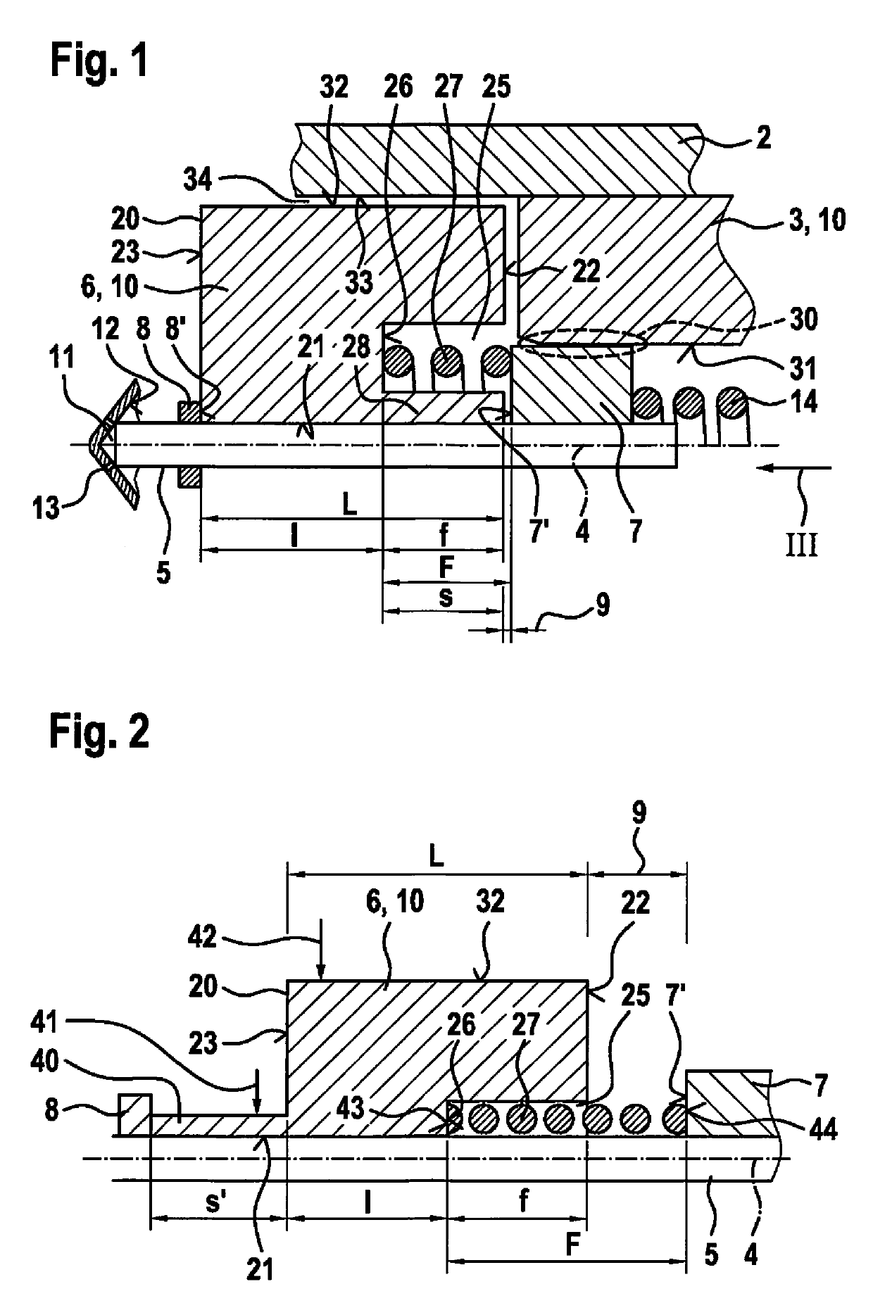
[0023]FIG. 1 shows a valve 1 for metering a fluid in an excerpted, schematic sectional illustration corresponding to a first exemplary embodiment. Valve 1 may, in particular, be designed as a fuel injector 1. A preferred application is a fuel injection system in which such fuel injectors 1 are designed as high pressure injectors 1 and used to inject fuel directly into assigned combustion chambers of the internal combustion engine. For this purpose, liquid or gaseous fuels may be used as the fuel. Accordingly, valve 1 is suitable for metering liquid or gaseous fluids.

[0024]Valve 1 includes a housing (valve housing) 2 in which an inner pole 3 is situated in a stationary manner. A longitudinal axis 4, which serves as a reference for the guidance of a valve needle 5 situated inside housing 2 here, is determined by housing 2. This means that, during operation, an orientation of valve needle 5 along longitudinal axis 4 is to take place.

[0025]An armature (solenoid armature) 6 is situated o...


PUM


Abstract

A valve for metering a fluid is described, which is used, in particular, as a fuel injector for internal combustion engines, including an electromagnetic actuator and a valve needle actuatable by the actuator, an armature of the actuator being guided on valve needle, a stop element which limits a movement of the armature relative to the valve needle being situated on the valve needle, and the armature including a spring receptacle which is open toward the stop element and in which a spring supported on the stop element is inserted. The valve needle is guided via the armature and/or the stop element along a longitudinal axis of a housing. Furthermore, as viewed along the longitudinal axis, a length of the spring receptacle is smaller than a spring length of the spring in the non-actuated initial state.

Description

FIELD OF THE INVENTION[0001]The present invention relates to a valve for metering a fluid, in particular to a fuel injector for internal combustion engines. Specifically, the present invention relates to the field of injectors for fuel injection systems of motor vehicles, in which preferably a direct injection of fuel into combustion chambers of an internal combustion engine takes place.BACKGROUND INFORMATION[0002]A valve for metering fluid is known from German Published Patent Application No. 10 2013 222 613. The known valve includes a solenoid for actuating a valve needle controlling a metering opening. The solenoid is used to actuate an armature movable on a valve needle. The armature has a borehole which abuts the valve needle and forms a spring receptacle for a prestroke spring.[0003]This design has the disadvantage that a guidance between the armature and the valve needle is only implemented over a short guide length.SUMMARY[0004]The valve according to the present invention ha...

Claims


Application Information

Patent Timeline
IPC IPC(8): F02M51/06F02M61/12F02M61/20
CPCF02M61/205F02M51/0685F02M51/0671F02M61/12F02M63/0075F02M55/008
Inventor UCAL, MURATGLASER, ANDREASHEINSTEIN, AXELSUENKEL, CHRISTIANMUELLER, FRANKABEL, JOERGBEHRINGER, MARCELBUEHNER, MARTINBOEE, MATTHIASREDLICH, NORBERTSCHRAMM, PETERCERNY, STEFAN
Owner ROBERT BOSCH GMBH
Why Eureka
Try Eureka