Gas turbine transition seal with hole through seal plate in groove of nozzle

a technology of transition seal and seal plate, which is applied in the field of gas turbines, can solve the problems of imposing problems, difficult to apply cooling structure in addition to sealing structure, etc., and achieve the effect of effective cooling

Active Publication Date: 2020-05-19
MITSUBISHI POWER LTD
View PDF16 Cites 0 Cited by
  • Summary
  • Abstract
  • Description
  • Claims
  • Application Information

AI Technical Summary

Benefits of technology

[0004]It is an object of the present invention to provide a gas turbine capable of effectively cooling, while sealing, a gap between a combustor transition piece and a turbine nozzle.
[0006]The present invention can effectively cool, while sealing, the gap between the combustor transition piece and the turbine nozzle.

Problems solved by technology

However, due to the anterior edge portion being thin, it is difficult to apply a cooling structure in addition to a seal structure.
This imposes a problem particularly on small-and-medium-sized gas turbines that are required to incorporate more compact components.

Method used


Image

  • Gas turbine transition seal with hole through seal plate in groove of nozzle
  • Gas turbine transition seal with hole through seal plate in groove of nozzle
  • Gas turbine transition seal with hole through seal plate in groove of nozzle

Examples


first embodiment

1. Gas Turbine

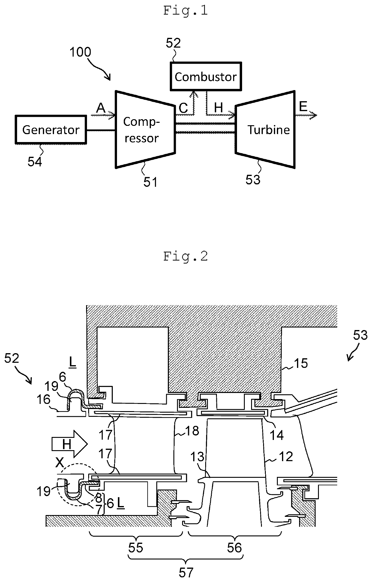
[0018]FIG. 1 is a schematic view of a gas turbine. This gas turbine 100 shown in FIG. 1 may have a relatively large size, but is here assumed to have a relatively small size smaller than a medium size. The gas turbine 100 includes a compressor 51, a combustor 52, and a turbine 53. The compressor 51 compresses air A drawn in via an intake part to thereby generate compressed air C at high pressure. The compressor 51 supplies the compressed air C to the combustor 52. The combustor 52 burns the compressed air C compressed by the compressor 51 with fuel to thereby generate combustion gas H at high temperature. The combustor 52 then supplies the combustion gas H to the turbine 53. The turbine 53 is driven by the combustion gas H generated by the combustor 52. The compressor 51 and the turbine 53 are coaxially coupled to each other. In addition, a load device (a generator 54 in the present embodiment) is coupled to the compressor 51 or the turbine 53. Rotational drive power a...

second embodiment

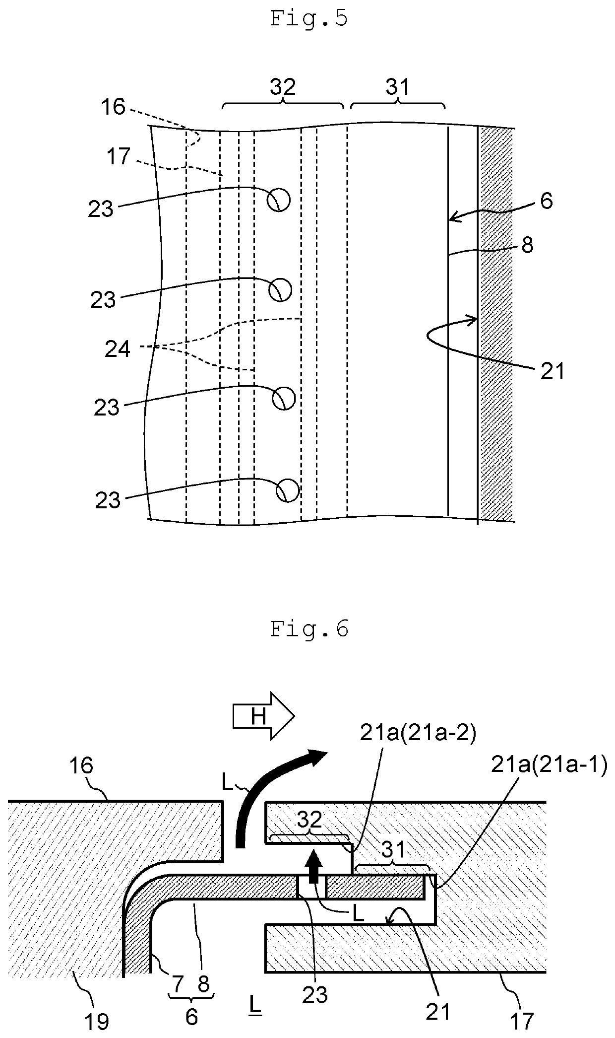
[0034]FIG. 6 is a view showing a seal structure in a gas turbine according to a second embodiment of the present invention. FIG. 6 corresponds to FIG. 3 that depicts the first embodiment. The present embodiment differs from the first embodiment in that the turbulence promoting member 24 is omitted. The present embodiment has configurations that are otherwise similar to the configurations of the first embodiment. The configurations of the present embodiment are applicable, if the cooling effect by the collision of the low-temperature fluid L jetted out from the through hole 23 against the high temperature-side inner wall surface 21a-2 is sufficient enough, without requiring the turbulence promoting member 24 for thermal load by the combustion gas H.

third embodiment

[0035]FIG. 7 is a view showing a seal structure in a gas turbine according to a third embodiment of the present invention. FIG. 7 corresponds to FIG. 3 that depicts the first embodiment. The present embodiment differs from the first embodiment in that a seal plate portion 8 of a seal member 6 is bent as viewed from the turbine rotating direction and that the turbulence promoting member 24 is omitted. The present embodiment has configurations that are otherwise similar to the configurations of the first embodiment.

[0036]The present embodiment includes a surface contact portion 8a-1 that constitutes a surface contact region 31 and a non-contact portion 8a-2 that constitutes a non-contact region 32. In the present embodiment, a high temperature-side inner wall surface 21a in a seal groove 21 has no step as viewed from the turbine rotating direction and extends flatly in the turbine axial direction, so that the surface contact portion 8a-1 makes a surface contact with the high temperatu...


PUM


Abstract

In a gas turbine in which a seal member seals a gap between a transition piece and a nozzle end wall in a turbine first stage, the transition piece and the nozzle end wall has a seal groove. The seal member includes a hook portion that slides in the turbine radial direction with respect to the flange and a seal plate portion inserted in the groove. The groove and the portion are configured to include a surface contact region in which a surface of the groove and the portion are in surface contact with each other, a non-contact region disposed on a side closer to the transition piece than the region, and a hole provided at the portion so as to face the surface in the groove across a gap in the region.

Description

BACKGROUND OF THE INVENTION1. Field of the Invention[0001]The present invention relates to a gas turbine.2. Description of the Related Art[0002]A gas turbine is configured to be driven by combustion gas generated as a working fluid at high temperature by burning using a combustor compressed air compressed by a compressor together with fuel. Components that are exposed to the turbine combustion gas at high temperature are thus required to be cooled as appropriate using as cooling air a low temperature fluid that has a temperature lower than a temperature of the combustion gas in order to prevent cracking or erosion from occurring as caused by oxidation or thermal stress. Additionally, the turbine and other components very often incorporate a split structure with the aim of facilitating maintenance service and replacement procedures, in addition to reducing stress concentration caused by thermal deformation. To prevent the combustion gas from entering a gap between components from a c...

Claims


Application Information

Patent Timeline
Patent Type & Authority Patents(United States)
IPC IPC(8): F01D11/00F01D9/02F02C7/28
CPCF01D11/005F02C7/28F01D9/023F05D2220/32F05D2240/55F01D11/003F01D25/12
Inventor HORIUCHI, YASUHIROHIGUCHI, SHINICHITAGAWA, HISATOSHINGAI, KENJIMIURA, TAKEMITSU
Owner MITSUBISHI POWER LTD
Why Eureka
Try Eureka