Spar hull load out method

a technology of spar hull and hull, which is applied in the direction of passenger handling apparatus, special-purpose vessels, vessel construction, etc., can solve the problems of insufficient water depth near the fabrication yard, insufficient water depth at the quayside to provide strake tip clearance, and hlv with spar on board goes through a minimal stability

Active Publication Date: 2012-06-14
J RAY MCCDERMOTT SA
View PDF10 Cites 5 Cited by
  • Summary
  • Abstract
  • Description
  • Claims
  • Application Information

AI Technical Summary

Benefits of technology

[0012]The present invention addresses the shortcomings in the known art and is drawn to a method and apparatus that yields sufficient bottom clearance for the strake tips of a large diameter spar. In addition,

Problems solved by technology

Therefore, on the larger diameter spars there is not sufficient water depth near the fabrication yard to provide bottom clearance for the strake tips.
When the HLV is ballasted downward to float off the spar, the HLV with the spar on board goes through a minimal stability when the deck of the HLV goes awash.
This occurs because the HLV loses most of its water plane area when its deck goes awash, and the spar is not yet picking up much water plane area.
However, there is insufficient water de

Method used


Image

  • Spar hull load out method
  • Spar hull load out method
  • Spar hull load out method

Examples


Embodiment Construction

[0032]The invention is a sequence of positions and operations of the U-tank acting in concert with the HLV.

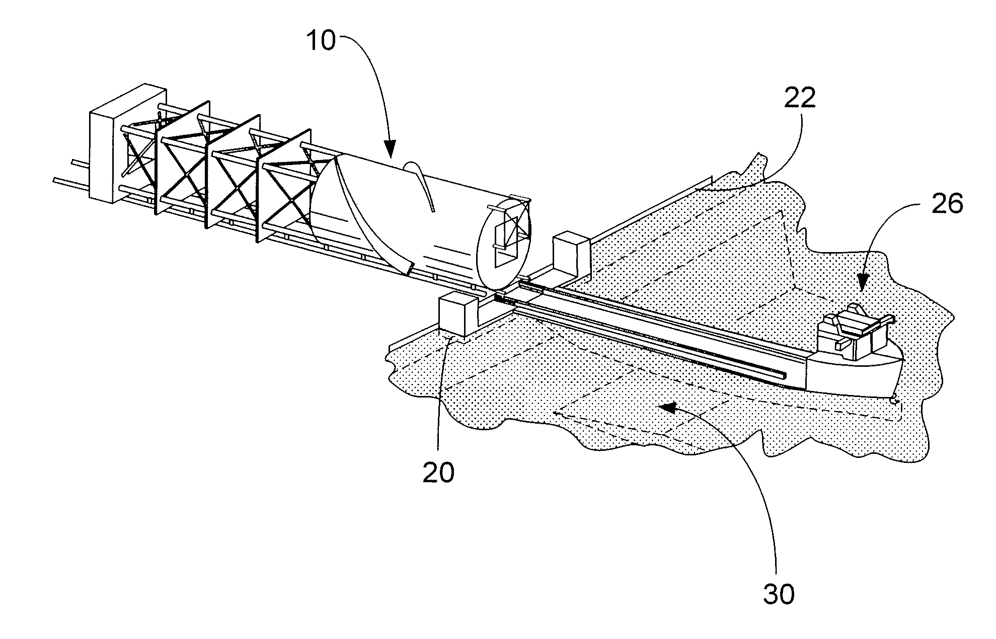
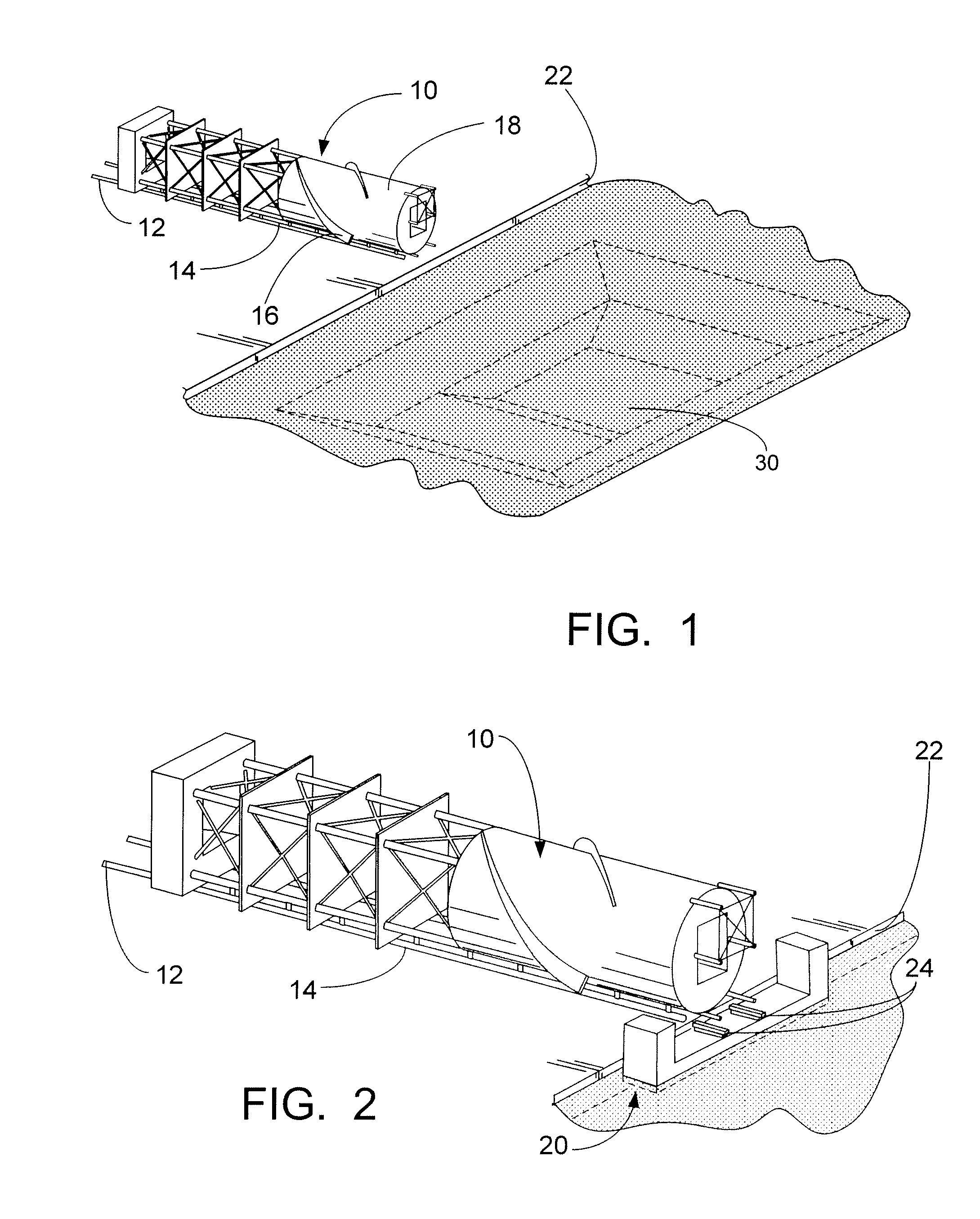
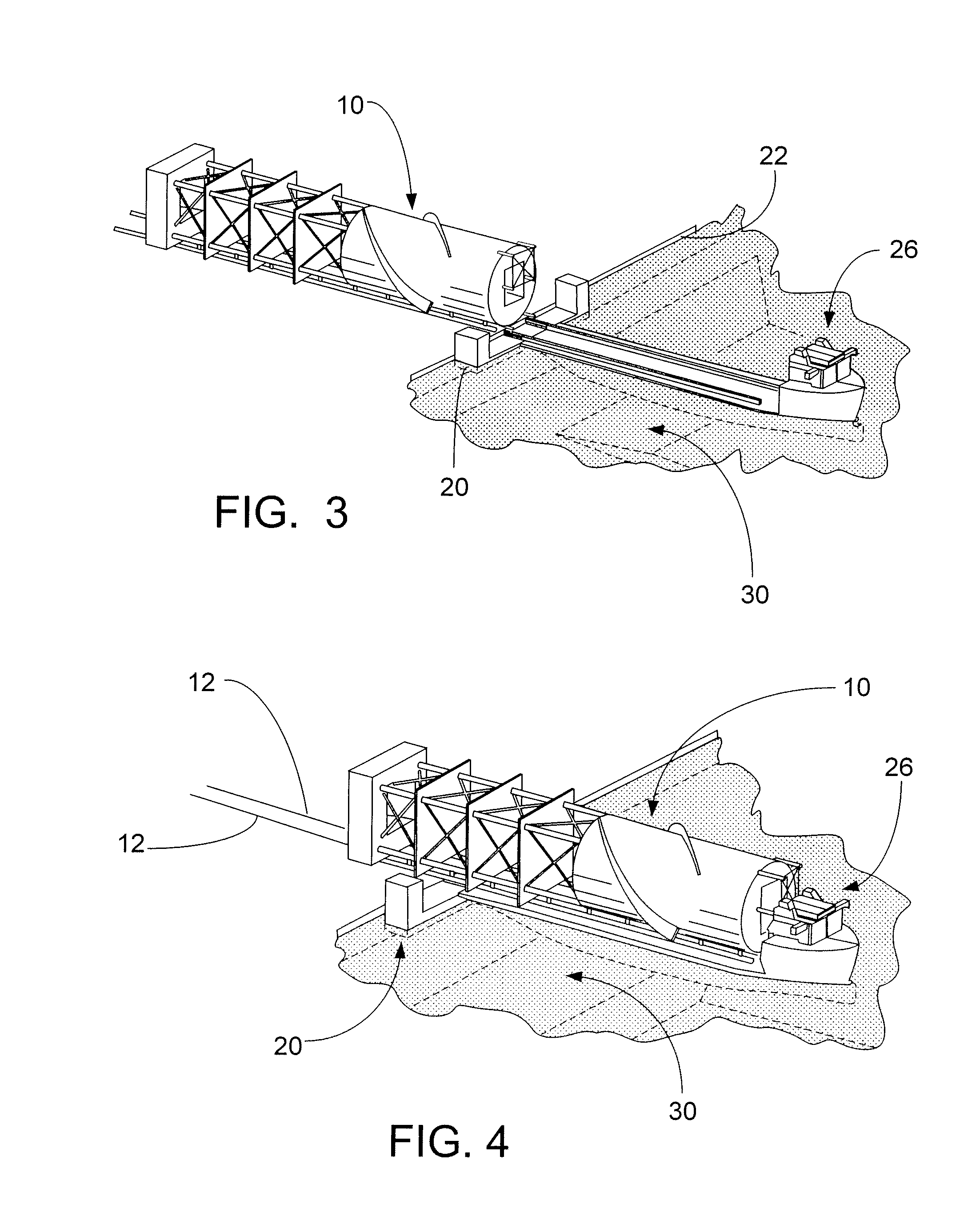
[0033]As seen in FIG. 1, a spar 10 is shown on the ways 12 ready for load out and perpendicular to the quay 22. The spar 10 is built on a cradle structure (not shown because it is obscured by the spar 10 in this view) that extends most of the length of the spar 10. Two parallel load out runners 14 are framed into the cradle. These runners 14 rest directly on the load out ways 12. Both the spar 10 and its cradle are loaded out together, the cradle runners 14 sliding along the load out ways 12.

[0034]The strakes 16 are shown as being incomplete on the bottom side of the hard tank 18. It should be understood that “incomplete”, in the offshore industry, may mean that the strakes on the bottom side of the hard tank are partial strakes that extend outward from the hard tank 18 only a portion of the specified distance as indicated above and the remainder of the strake will be installed...


PUM


Abstract

A load out and float off method for a spar type structure or another structure such as a deck. The invention enables the load out and float off of a large diameter spar using existing Heavy Lift Vessels (HLV's). A U-shaped tank (U-tank) is utilized to artificially extend the length of the HLV and provide supplemental buoyancy to help lift the spar off the land ways. The U-tank provides supplemental buoyancy and water plane area to float the spar off the HLV. After HLV departure the U-tank is moved and placed beneath an adapter frame on the spar's hard tank. The U-tank is ballasted upward to reduce the hard tank draft and have the strake tips clear the channel bottom. The spar can then be brought alongside the fabrication yard quay for additional work and then towed down the channel to the open sea.

Description

PRIORITY CLAIM[0001]This application claims priority from Provisional Application No. 61 / 422,712 filed Dec. 14, 2010.FIELD AND BACKGROUND OF INVENTION[0002]The invention is generally related to floating offshore structures and more particularly to the load out, float off, and channel tow of a spar type hull.[0003]There are a number of spar hull designs available in the offshore drilling and production industry. These include the truss spar, classic spar, and cell spar. The term spar hull structure described herein refers to any floating structure platform, which those of ordinary skill in the offshore industry will understand as any floating production and / or drilling platform or vessel having an open centerwell configuration.[0004]The spar supports a topside structure and comprises a hard tank, truss section, and a soft tank. In the case of the classic spar, the hard tank and soft tank are connected by a cylinder instead of a truss. The hard tank supplies the majority of the buoyan...

Claims


Application Information

Patent Timeline
IPC IPC(8): B65G67/60
CPCB63B27/02B63B9/00B63B35/003B63B71/00B63B27/19B63B27/00B63B35/42B65G67/60
Inventor HANEY, JAMES ALLANLEOW, BEE-LAY
Owner J RAY MCCDERMOTT SA
Why Eureka
Try Eureka