Wind deflector

a wind deflector and a technology of a wing are applied in the field of wind deflectors to achieve the effect of reducing air draft and improving airflow conditions

Active Publication Date: 2014-08-12
DR ING H C F PORSCHE AG
View PDF22 Cites 3 Cited by
  • Summary
  • Abstract
  • Description
  • Claims
  • Application Information

AI Technical Summary

Benefits of technology

[0007]The invention relates to a shell-shaped wind deflector mounted on the vehicle seat to improve airflow conditions to the left and right of the head of the driver or front seat passenger. Each wind deflector is arranged in the region of a headrest or a head receptacle on the vehicle seat and is attached thereto by connecting elements on the sides and at the rear of the seat. The shell-shaped wind deflector comprises a rear wall that extends around the headrest of the vehicle seat. The rear wall of each wind deflector is adjoined by lateral air guiding elements with upright protective faces arranged to run in the direction of travel. A receptacle space is formed between the lateral air guiding elements, in a region in front of the headrest and reduces a draft of air for the head of the seated person.
[0008]An upper roof-shaped air guiding element may adjoin the rear wall of the wind deflector and has a protective face arranged approximately in a horizontal plane to extend over the headrest in the direction of travel. The protective faces of the wind deflector are oriented toward the front on both sides to prevent the air stream coming from the side and from the rear from impacting directly on the neck and head region of the driver or front seat passenger. Thus, the flow conditions in the neck region to the left and right of the head are improved. The lateral protective faces of the wind deflector substantially reduce the lateral draft of air in the transverse direction relative to the direction of travel and in the direction of the driver or front seat passenger. Additionally, the upper roof-shaped protective face impedes an air stream coming from above in the transverse direction relative to the direction of travel.
[0009]The windbreak preferably is a single-piece hard shell that is shaped around the headrest or the vehicle seat. Additionally, the rear wall extends around the vehicle seat to form a coherent, single-piece structural unit with the lateral air guiding elements. The rear wall also preferably forms a coherent, single-piece structural unit with the lateral air guiding elements and the upper, roof-shaped air guiding element. As a result, the wind deflector is a dimensionally stable half shell, and a wide variety of coloring is possible, such as in a vehicle color, CFK look etc. The accessory can be enhanced as desired by a combination with aluminum or other materials.
[0010]The lateral air guiding elements of the wind deflector preferably have protective faces in the shape of an ear. The protective faces preferably extend into the protective face of the upper roof-shaped air guiding element and have a concavely running arcuate edge. The two lateral air guiding elements diverge from one another, when viewed in the direction of travel. Additionally, the air guiding elements have a V-shape and the protective faces of the air guiding elements run in a protruding fashion with respect to the headrest and surround the head region or the headrest of the vehicle seat laterally. This configuration of the wind deflector provides optimum lateral and upper enclosure of the head of the seated person so that the air flow can be kept away from the head and the neck, as far as possible, and disruptive drafts of air are avoided.
[0013]The invention offers a significant advantage over conventional wind deflectors that are attached to the bodywork or to the interior fittings because an additional side protection is formed by protective faces that project forward on both sides next to the seat. The roof-shaped air guiding element provides additional protection from above. Additionally, the attachment to the seat keeps the distance of the wind deflector from the seated person constant irrespective of the seating position in the vehicle.

Problems solved by technology

Additionally, the upper roof-shaped protective face impedes an air stream coming from above in the transverse direction relative to the direction of travel.

Method used


Image

  • Wind deflector
  • Wind deflector
  • Wind deflector

Examples


Embodiment Construction

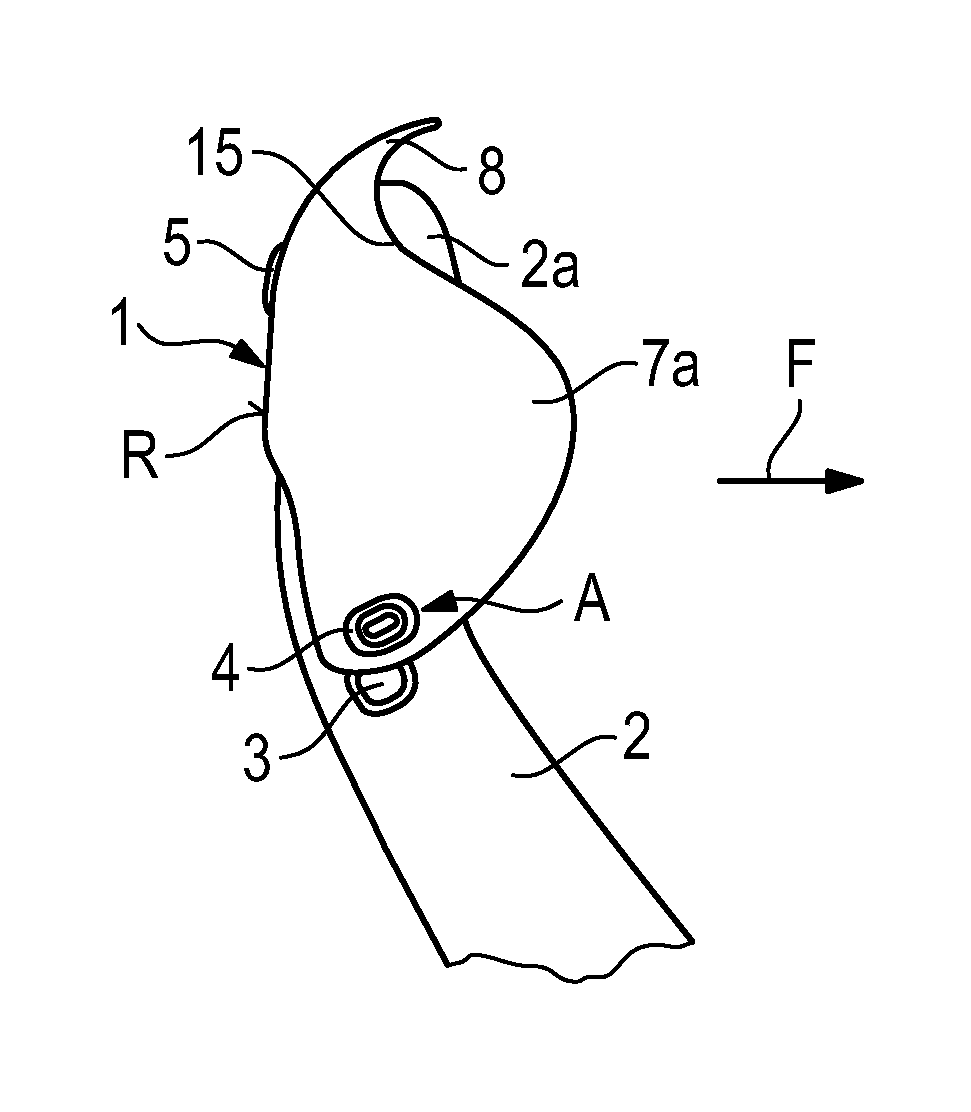
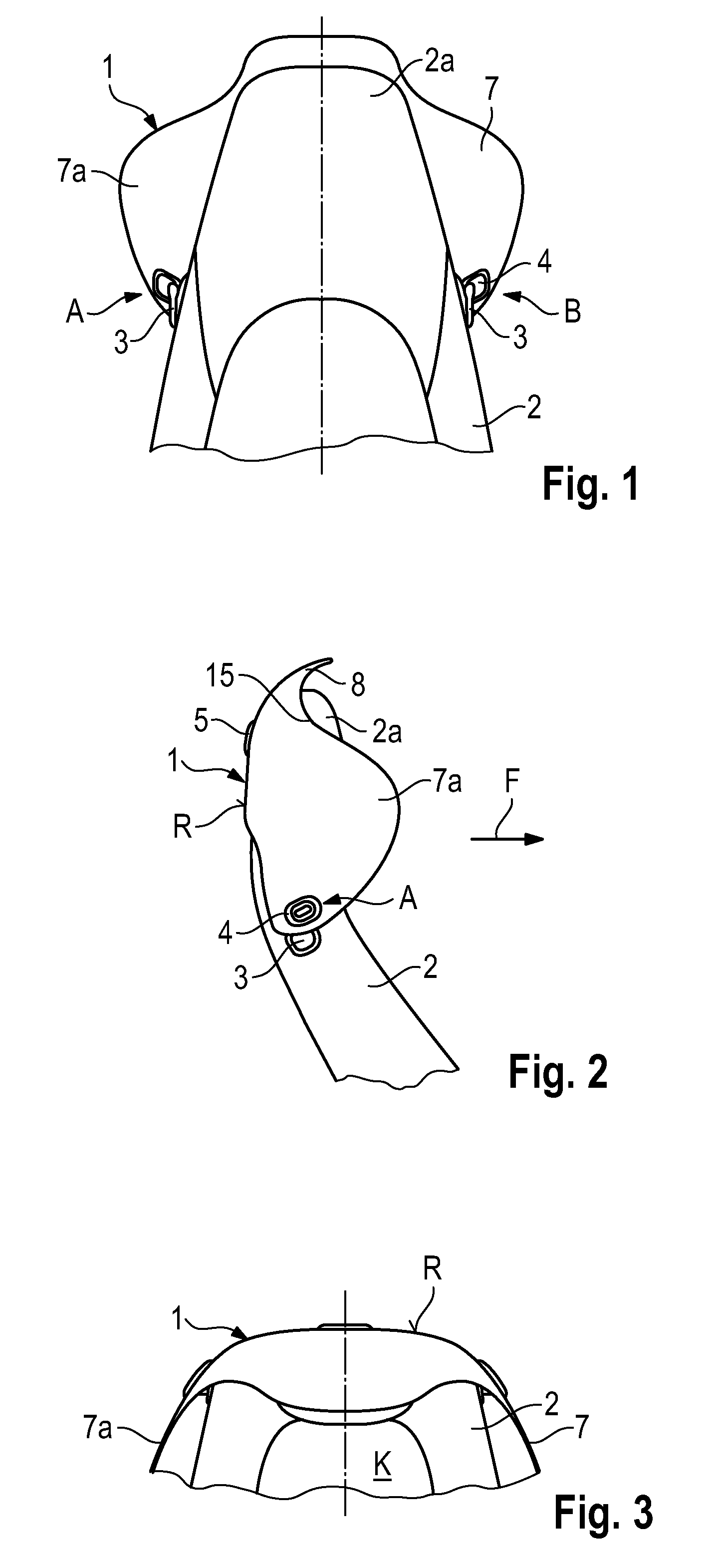
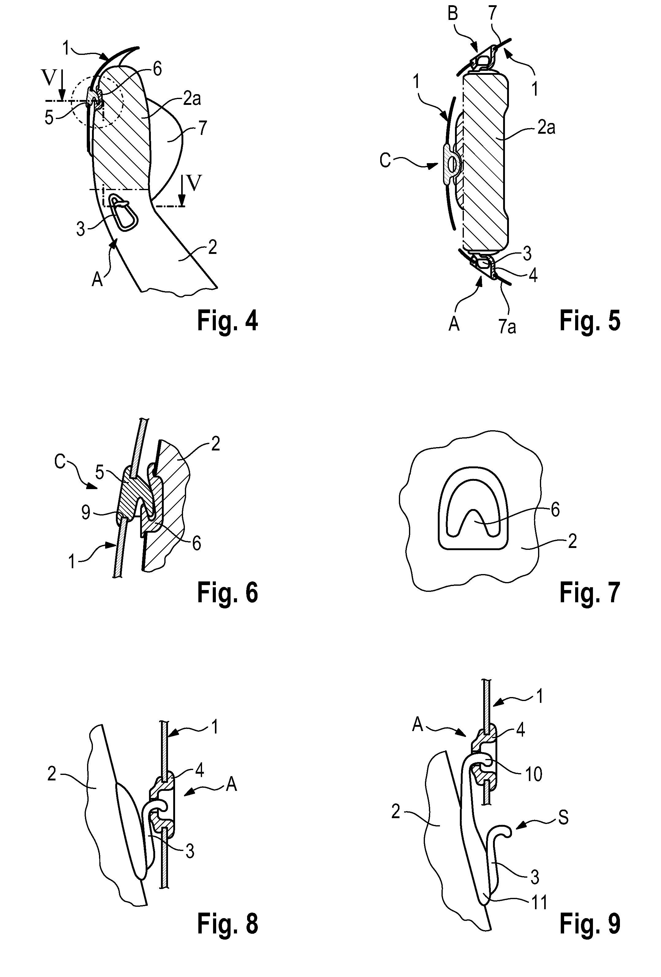
[0029]A wind deflector 1 for a convertible vehicle is arranged in the region of a headrest 2a or the head region of each vehicle seat 2. Attachment to the seat 2 is carried out by connecting elements A, B and C at predetermined attachment points on the sides and at a rear side of the seat 2.

[0030]The wind deflector 1 is in the form of a shell and comprises a rear wall R that extends around the headrest 2a of the seat 2. The rear wall R is adjoined by lateral air guiding element 7, 7a with upright protective faces arranged to run in the direction F of travel. A space K between the two air guiding elements 7, 7a in front of the headrest 2a accommodates a head of a driver or a front seat passenger and reduces a draft of air.

[0031]The wind deflector 1 has an upper roof-shaped air guiding element 8 that joins the rear wall R. The upper roof-shaped air guiding element 8 has a protective face arranged approximately in a horizontal plane and extends over the headrest 2a in the direction F o...


PUM


Abstract

A wind deflector for a convertible vehicle is connected to a vehicle seat in the region of a headrest. The wind deflector is attached removably to the vehicle seat by connecting elements. A rear wall of the wind deflector extends around the headrest of the vehicle seat and is adjoined by, in each case, lateral air guiding elements with upright protective faces arranged running in the direction of travel and form between them, in a region in front of the headrest, a space that reduces a draft of air. In a further embodiment, the wind deflector can also be provided with a roof-shaped air guiding element.

Description

CROSS REFERENCE TO RELATED APPLICATION[0001]This application claims priority under 35 USC 119 to German Patent Appl. No. 10 2011 056 073.4 filed on Dec. 6, 2011, the entire disclosure of which is incorporated herein by reference.BACKGROUND OF THE INVENTION[0002]1. Field of the Invention[0003]The invention relates to a wind deflector arranged behind vehicle seats of a convertible vehicle.[0004]2. Description of the Related Art[0005]U.S. Pat. No. 3,246,923 discloses a semi-spherical shell adjustably attached to a backrest of a vehicle seat for deflecting a draft of air. The shell has lateral protective faces and an upper protective face that extends partially around the head of a driver or front seat passenger.[0006]The object of the invention is to provide a wind deflector for an open motor vehicle, such as a convertible vehicle, to protect against undesired airflows for the head or the neck and neck region.SUMMARY OF THE INVENTION[0007]The invention relates to a shell-shaped wind de...

Claims


Application Information

Patent Timeline
Patent Type & Authority Patents(United States)
IPC IPC(8): A47C7/62
CPCB60J7/223B60N2/4876B60N2002/4405B60N2/879B60N2002/905B60N2/803
Inventor GAUSRAB, KLAUS
Owner DR ING H C F PORSCHE AG
Why Eureka
Try Eureka