Camouflage structure capable of altering its appearance

a technology of camouflage structure and appearance, applied in the field of camouflage structure, can solve the problems of complicated structural design, dangerous, traditional pixelized camouflage structure,

Active Publication Date: 2012-06-14
IND TECH RES INST
View PDF16 Cites 25 Cited by
  • Summary
  • Abstract
  • Description
  • Claims
  • Application Information

AI Technical Summary

Problems solved by technology

It can be imagined how dangerous it is if the soldier in the different combat fields wears the combat uniform with inadequate camouflage patterns.
However, the pattern of MultiCam® is still a combination and arrangement of millions of small blocks with unchangeable colors, not changeable colors.
However, the traditional pixelized camouflage structures have considerable problems, such as complicated structural designs, difficult to drive and high cost of fabrication, and not suitable for mass productions.

Method used


Image

  • Camouflage structure capable of altering its appearance
  • Camouflage structure capable of altering its appearance
  • Camouflage structure capable of altering its appearance

Examples


first embodiment

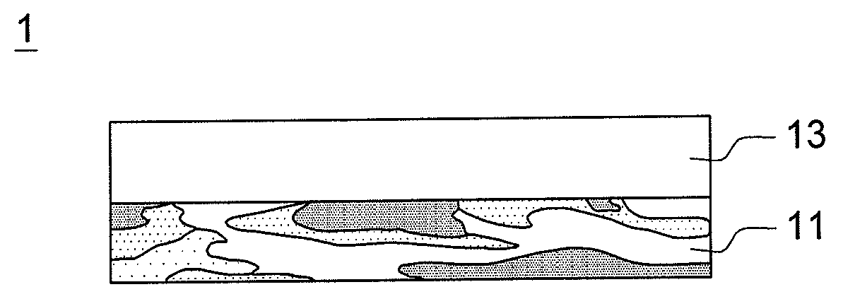
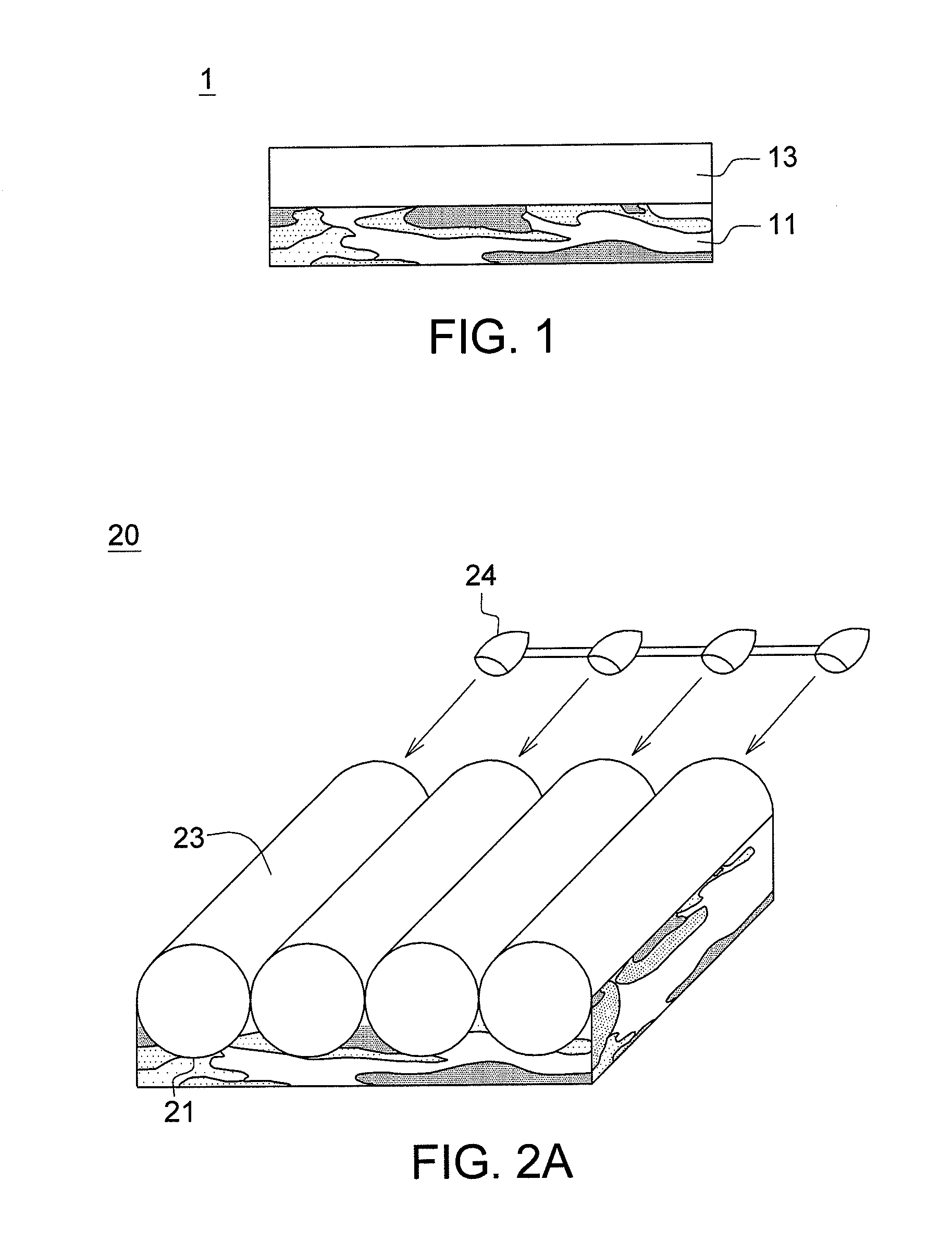
[0023]FIG. 1 simply illustrates a camouflage structure according to the first embodiment of the disclosure. The camouflage structure 1 of FIG. 1 includes a camouflage graphic layer 11, and a color-changing layer 13 disposed on the camouflage graphic layer 11. The color-changing layer 13 is able to change the color by a driving method, such as one of electric driving methods, optical driving methods, thermo-driving methods, and magnetic driving methods. The camouflage structure 1 originally presents a first color state. After the color-changing layer 13 alters the color, the camouflage structure 1 would present a second color state.

[0024]In an embodiment, the camouflage graphic layer 11 is a greenish (woodland) camouflage graphic layer. A transparent or semi-transparent color-changing layer 13, able to change color between transparent and red, could be disposed on the greenish camouflage graphic layer 11. When the transparent or semi-transparent color-changing layer 13 shows no color...

second embodiment

[0038]FIG. 6 simply illustrates a camouflage structure according to the second embodiment of the disclosure. The camouflage structure of FIG. 6 at least comprises a greenish camouflage graphic layer 61 made of at least one of chromic materials with red-shift characteristics (which means the greenish camouflage graphic layer 61 consists of different colors of chromic materials with reversible red-shift characteristics). The colors or tones of patterns of the greenish camouflage graphic layer 61 could comprise green, yellow and brown. Examples of the chromic materials of the greenish camouflage graphic layer 61 include electrochromic materials, photochromic materials, thermochromic materials and magnetochromic materials. The camouflage structure of the second embodiment can be operated by electric drive, optical drive, thermal drive or magnetic drive, corresponding to the materials of the chromic materials. When the greenish camouflage graphic layer 61 is red-shifted by an appropriate...


PUM

PropertyMeasurementUnit
color stateaaaaaaaaaa
coloraaaaaaaaaa
conductiveaaaaaaaaaa

Abstract

A camouflage structure, capable of altering its appearance, comprises a camouflage graphic layer and a color-changing layer disposed on the camouflage graphic layer. Originally, the camouflage structure presents a first color state. After the color-changing layer changes the color by driving methods, the camouflage structure presents a second color state. For example, a transparent or semi-transparent color-changing layer able to reflect or emitting red light could be disposed on the woodland camouflage graphic layer, which allows for the overall appearance to change from the greenish woodland camouflage to the brownish desert camouflage. Alternatively, the camouflage structure could comprise a greenish camouflage graphic layer made of material with red-shift characteristics, which means the greenish camouflage graphic layer consists of different colors of chromic materials with reversible red-shift characteristics. The greenish camouflage graphic layer can be red-shifted by driving methods so as to present an appearance of brownish desert camouflage.

Description

[0001]This application claims the benefit of Taiwan application Serial No. 99142892, filed Dec. 8, 2010, the subject matter of which is incorporated herein by reference.BACKGROUND[0002]1. Field of the Invention[0003]The disclosure relates in general to a camouflage structure, and more particularly to a camouflage structure capable of altering its appearance.[0004]2. Description of the Related Art[0005]It has been one of the major concerns of soldiers that whether or not they were being concealed in the combat field to have better surviving chance. Camouflage, having capability of concealment and deception, works by tricking the eye and brain and how they recognize color, volume and shape. Because only a small area of the eye perceives color, the brain does a lot of filling in as it processes images. Camouflage takes advantage of this by helping an observer see the pattern as part of the background. Generally, soldiers in the different combat fields requires different combat uniforms...

Claims


Application Information

Patent Timeline
Patent Type & Authority Applications(United States)
IPC IPC(8): B32B3/10B32B3/00
CPCY10S428/913Y10S428/919F41H3/00F41H3/02B32B2307/402B32B5/12Y10T428/24802B32B2307/202B32B2307/40B32B2437/00B32B2571/02Y10T428/24322B32B5/26
Inventor TSAI, CHEN-CHU
Owner IND TECH RES INST
Why Eureka
Try Eureka