Self-Contained Munition Gas Management System

a gas management system and self-contained technology, applied in the field of vertical missile launchers, can solve the problems of high cost of launcher-related modifications, integration solutions and advantages provided by als that do not address the specific needs of munitions, and achieve the effect of low cost of integration testing

Inactive Publication Date: 2012-06-21
LOCKHEED MARTIN CORP
View PDF7 Cites 8 Cited by
  • Summary
  • Abstract
  • Description
  • Claims
  • Application Information

AI Technical Summary

Benefits of technology

[0031]The GMS provides a lower cost of integra...

Problems solved by technology

A major roadblock to providing new munitions capability to naval fleets is the extremely high cost of launcher-related modifications.
Additionally, integrating a new munition typically requires re-qualifying th...

Method used


Image

  • Self-Contained Munition Gas Management System
  • Self-Contained Munition Gas Management System
  • Self-Contained Munition Gas Management System

Examples


Embodiment Construction

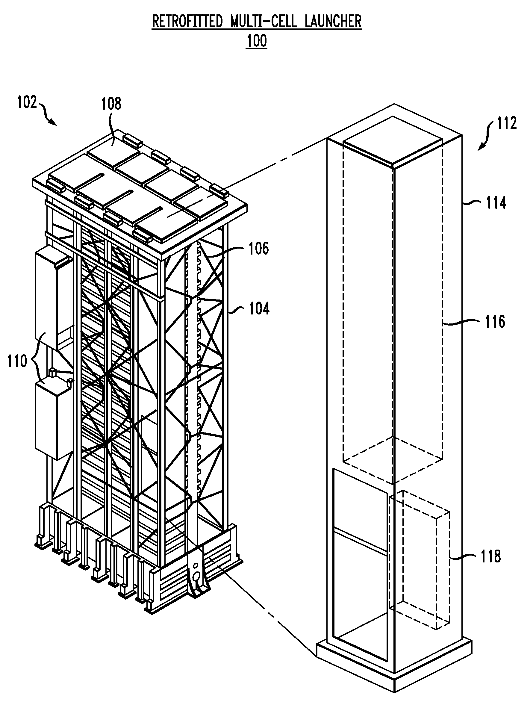
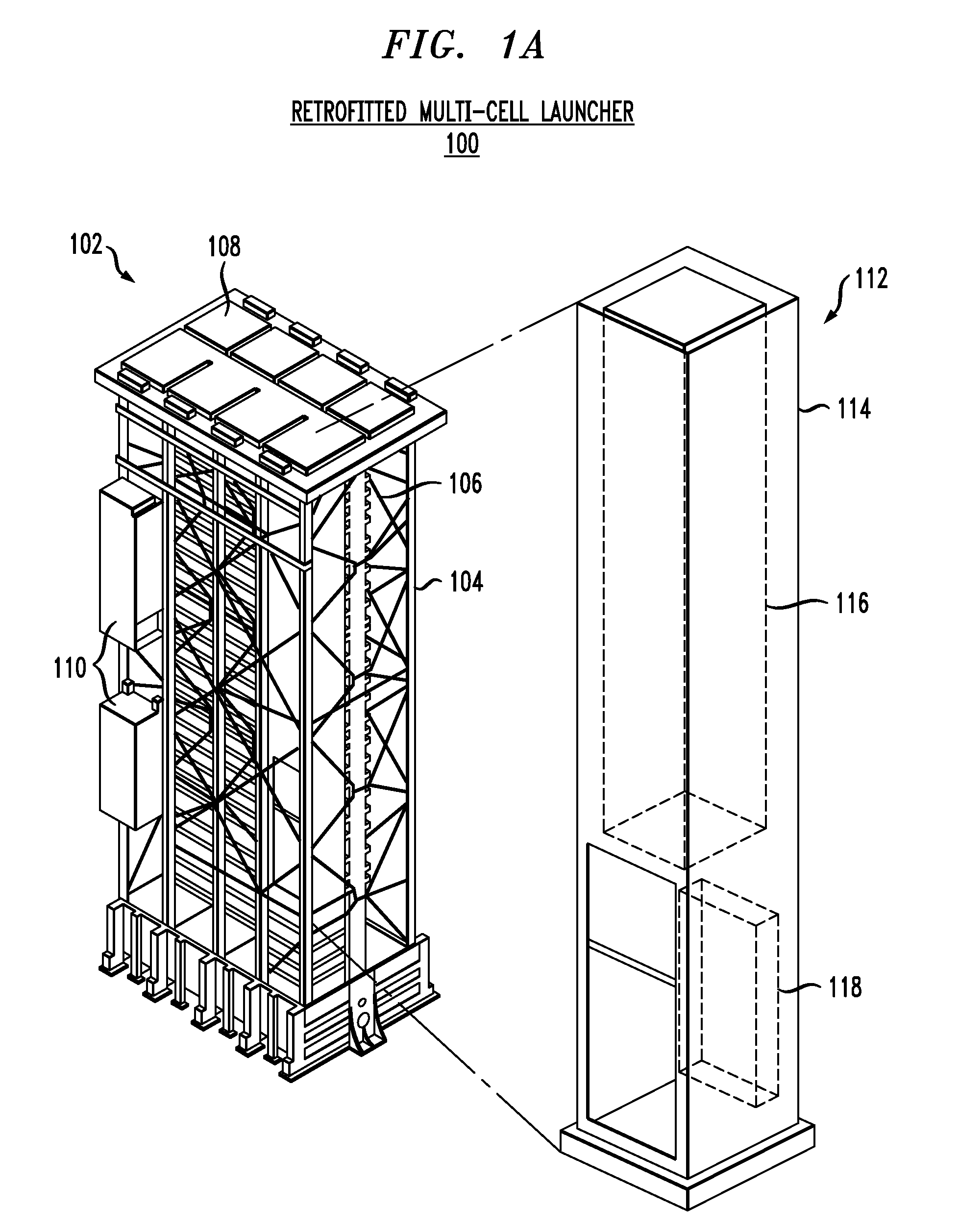
[0059]The following terms are defined for use in this disclosure and in the accompanying claims:[0060]The term “electrically-connected” means that two objects are in direct electrical contact without any intervening elements. In other words, the region of contact between the two objects remains at a substantially uniform voltage for substantially any current (neglecting any voltage drop due to the resistivity of the physical connection medium, such as a wire).[0061]The term “electrically-coupled” means that two objects are in electrical contact. This can be via direct physical contact (e.g., a plug in an electrical outlet, etc.), via an electrically-conductive intermediate (e.g., a wire that connects devices, etc.), or via intermediate devices, etc. (e.g., a resistor electrically connected between two other electrical devices, etc.).[0062]The term “enhanced munitions adapter” means the structure that accommodates a plurality of gas management systems (GMSs). It will be clear to thos...


PUM


Abstract

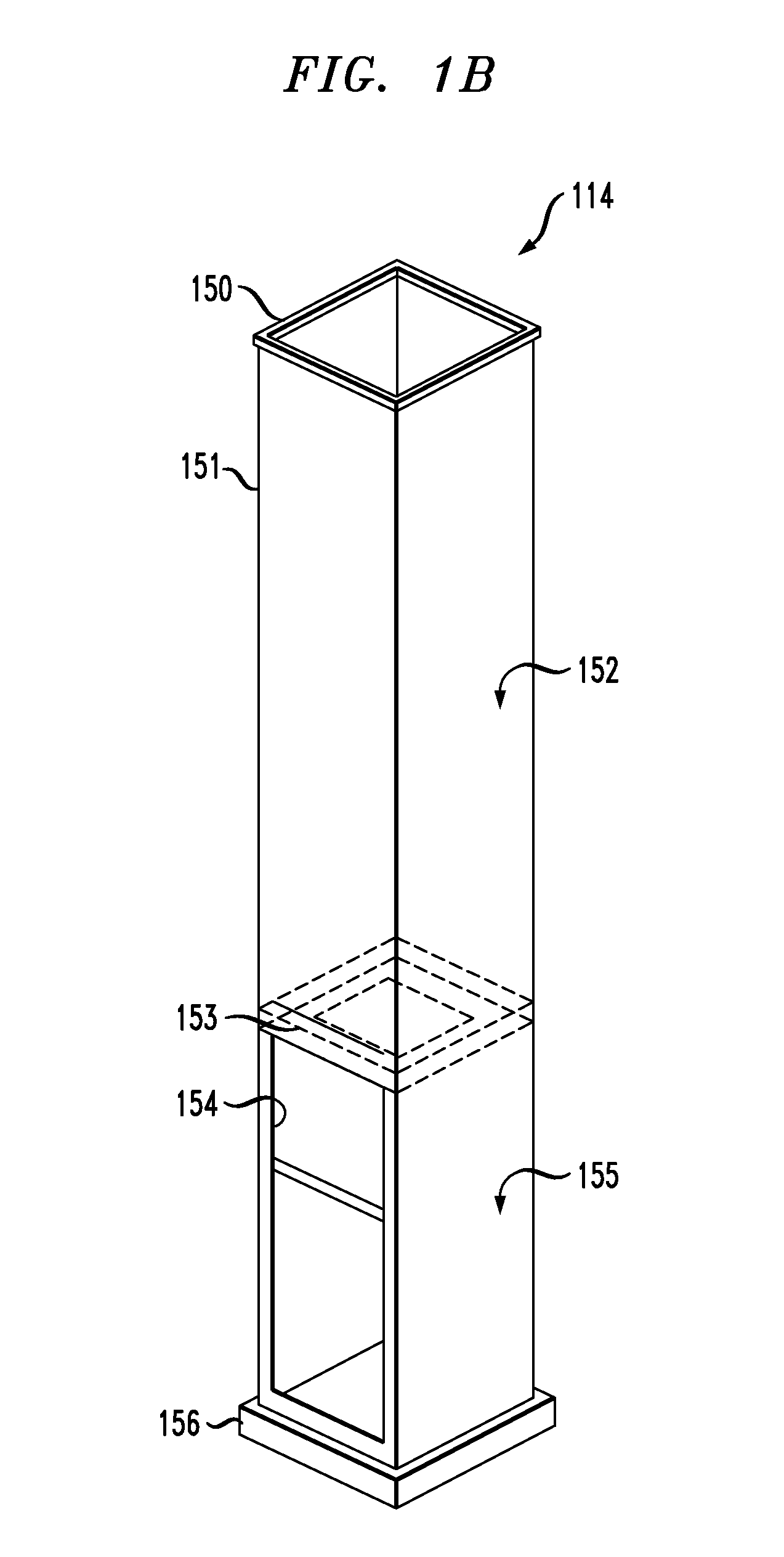
An apparatus is disclosed that is a self-contained gas management system (hereinafter “GMS”) that accommodates individual canisters of highly energetic small munitions, but is not so limited. By decoupling the gas management system for a given munition from an adjacent munition, the risk of downing a multi-pack launcher or munition adapter is reduced. Thermal wear, overheating, restrained firing and aft closure debris can be isolated through the separation of gas management systems. In addition, the GMS allows for ease of replenishment and maintenance of a given sub-cell of a multi-pack system. The GMS works with existing munitions and canisters without the need to modify them. Each GMS is dimensioned to fit the canistered munition it receives as well as the launch system with which it is used. The illustrative GMS comprises a plenum, and a first and a second uptake structure. The plenum receives the exhaust from the canistered munition when the munition fires. The plenum is fluidically coupled to the first and second uptake structures. The uptake structures in the illustrative embodiment receive the missile exhaust from the plenum and vent the exhaust to the atmosphere. In the illustrative embodiment, the first and second uptake structures are disposed along opposite sides of the canistered munition, flanking it.

Description

FIELD OF THE INVENTION[0001]The present invention relates to missile launchers, and more particularly to vertical missile launchers.BACKGROUND OF THE INVENTION[0002]Modern warships use guided missiles as their principal offensive and defensive weapons. Since a naval engagement may be protracted, a warship must have many missiles available for immediate launch. This need has been addressed by multiple-missile launchers, in which plural launch cells (e.g., eight cells, etc.) are loaded with missiles that can be individually launched.[0003]There is also a need to launch, from a single multiple-missile launcher, missiles of different mission type. This need has been met, for example, by the below-deck, vertical MK 41 and MK 57 missile launchers. These launchers accept canisterized (or canistered) missiles, wherein the missiles can be one of several types. The canisters are loaded into corresponding canister-holding chambers or cells in the missile launcher. Each canistered missile has a...

Claims


Application Information

Patent Timeline
IPC IPC(8): F41F3/073
CPCF41F3/073F41F3/0413
Inventor SKURDAL, DANIEL A.SNEDIKER, JOHN
Owner LOCKHEED MARTIN CORP
Why Eureka
Try Eureka