
Docking aid apparatus with utility implement

a technology of mooring apparatus and mooring rod, which is applied in the direction of boat hooks, waterborne vessels, vessel construction, etc., can solve the problems of inefficient hit-and-miss methods, inability to successfully loop the piling from the boat, and the difference in the physical dimensions of the dock, so as to reduce the wear and tear at the weak points and be more durable

Inactive Publication Date: 2012-06-21
STANLEY ROBERT
View PDF0 Cites 10 Cited by
  • Summary
  • Abstract
  • Description
  • Claims
  • Application Information

AI Technical Summary

Benefits of technology

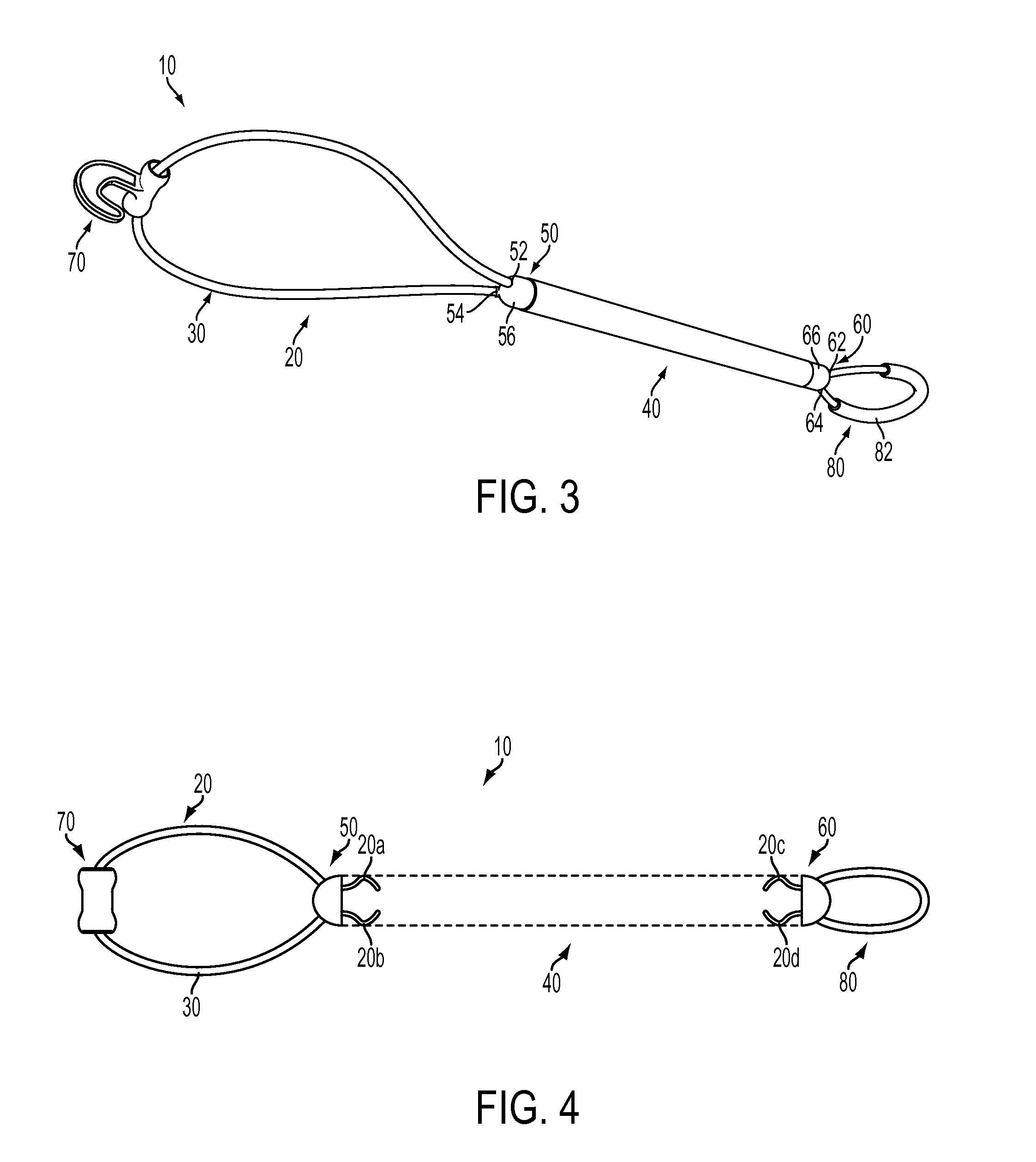
[0009]The present invention preserves the advantages of the apparatus in the prior art, and improves upon them. In addition, it provides one or more self supporting loops formed from a tensile member. The loops may have attachments that are securely and firmly fastened to accommodate multipurpose use. The stiffness of the loop and the fastening allows the loop and the attachment to be used from a distance, without the need for a person to manually connect the attachment to a docking element. It also removes the need for the loop to be thrown around a piling in a hit-or-miss process. In at least one embodiment, the tensile member may pass through a hollow shaft to form loops at either end of the shaft, thereby allowing the tensile forces to pass through the tensile member and be transferred between the docking element and the operator. This substantially reduces the wear and tear at the weak points of the docking apparatus, making it more durable. This invention is therefore a substantial improvement over the apparatus of the prior art.
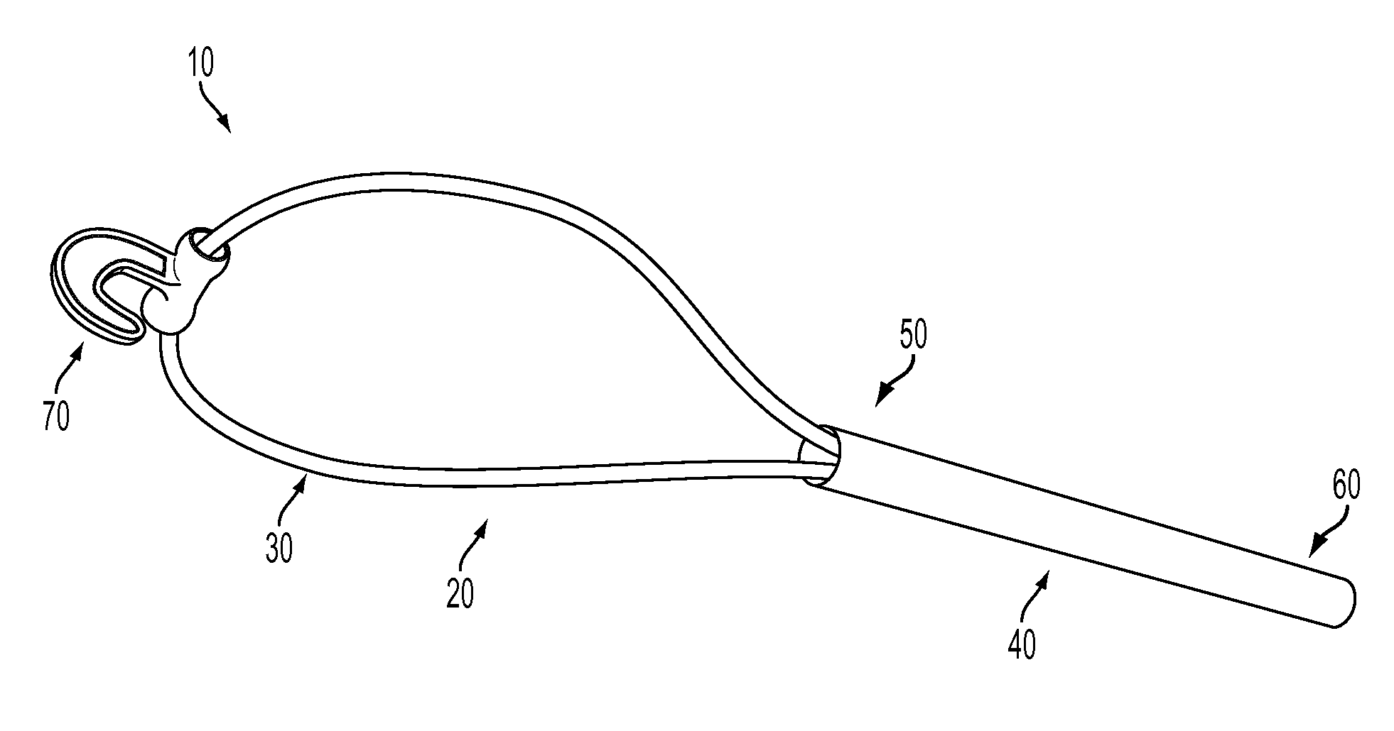
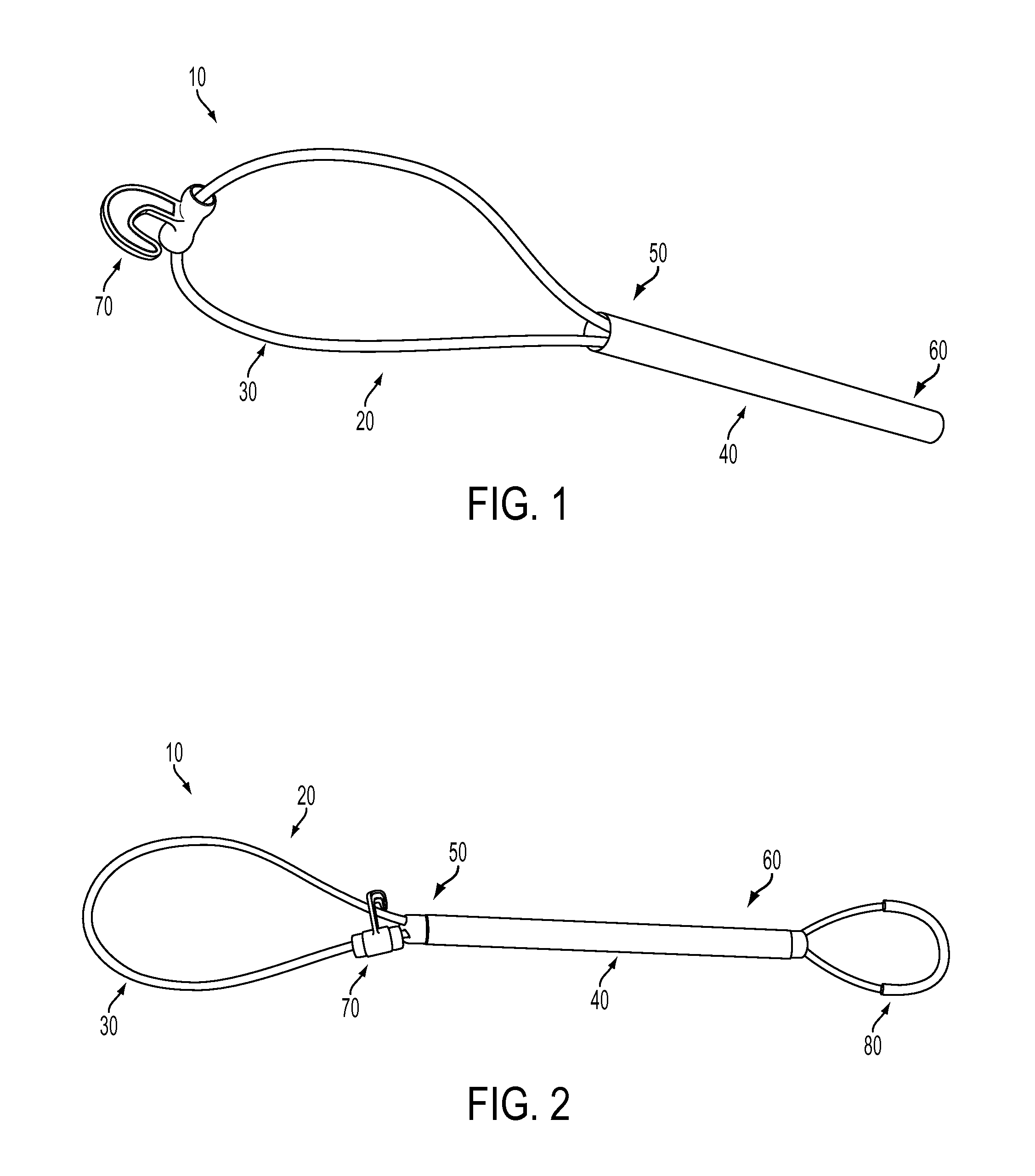
[0010]One embodiment of the invention consists of an elongated shaft with a self-supporting loop made of tensile member at one end. The loop may be formed by fixing both ends of the tensile member to the body of the shaft, or to the body of the tensile member itself. The tensile member is sufficiently stiff such that the loop maintains its form when extended horizontally, and does not hang or otherwise deform, as a simple rope would. The loop may have a utility implement with an attached utility tool such as a hook, a closable clasp, a clamp that hooks and unhooks, or a pair of jaw members that close around a mooring member. This tool may be interchangeable. The utility tool may be used, for instance, to pull closer to the dock; to pull alongside another watercraft; or to clamp onto a docking pile where the loop may not be effective as a docking aid. The tool may also be used to retrieve objects from the water that have fallen overboard. In some embodiments, the elongated shaft is hollow and the tensile member may pass through this shaft. The tensile member may form a handle or another self-supporting loop, at the other end of the elongated shaft. This second self-supporting loop may be used as a handle to maneuver the docking apparatus, or to pull. The handle may be padded for added comfort and for an improved grip. This second loop may also be used to connect to the mooring member on the watercraft or boat. An important and favorable use may be around areas of boat congestion. This could be around fuel docks where someone extends assistance from the dock to the boats to get them pulled closer to the fuel dock to tie off more safely and quickly.

Problems solved by technology

This may be either due to the tendency of the vessel to drift, or it may be in areas of boat congestion.
Given the small interval of time available to successfully dock the boat under such circumstances, this hit-and miss method is inefficient, and under certain conditions of high wind and / or swift currents, could also be dangerous.
Another common problem encountered by operators of boats and other watercrafts is the difference in the physical dimensions of the docks.
For instance, some pilings may be too tall to be successfully looped from a boat.
Two major drawbacks of this apparatus are that the tensile forces acting on the rope may rupture the tubular element.
Also, the clasp is not securely connected to the loop, thereby requiring manual intervention to secure the clasp to the mooring element.
This apparatus also does not allow for other attachments to be securely connected to the loop or loops.
The patents mentioned above fail to adequately solve the problems associated with docking a boat.

Method used


Image

  • Docking aid apparatus with utility implement
  • Docking aid apparatus with utility implement
  • Docking aid apparatus with utility implement

Examples


Embodiment Construction

[0029]This apparatus aids in docking a boat without assistance from the shore, and without having to disembark to manually aid in the docking While the invention will be described in connection with certain embodiments, there is no intent to limit the invention to these embodiments. On the contrary, the intent is to cover all alternatives, modifications and equivalents as included within the spirit and scope of the invention. Various changes may be made to the function and arrangement of the elements described herein, without changing the scope of the invention being disclosed. It should be noted that the following description serves to teach at least one instance of how the various elements may be arranged to achieve the stated goals of this invention.

[0030]With reference to FIG. 1, a docking aid apparatus 10 may be used to acquire connection to a docking pole or another watercraft. The apparatus may also be used to grab a distant docking pole or another watercraft to pull closer t...


PUM


Abstract

This invention is for a docking aid to help dock a boat to a docking post, or to pull a boat closer to the shore. It comprises of a shaft and a tensile member. The tensile member may pass through the shaft and form one or more loops at the ends of the shaft. One loop may be used to dock to a docking pole, while a second loop may be used as a handle to pull, or to loop around another docking element. At least one loop may have a utility implement with an attached tool. This tool may be used to grab a docking post from a boat, to grab an inbound boat from a dock, to pull closer to a second boat, or to grab objects out of the water that may have fallen overboard. The docking aid may also be floatable.

Description

BACKGROUND OF THE INVENTION[0001](a) Technical Field of the Invention[0002]The present invention relates to a docking or mooring apparatus used to safely reach and pull to a dock or to a second boat, in a safe, controlled and extended manner. The dock or the second boat may be equipped with different docking elements, such as a piling, a cleat, a ring, or some other element. These docking elements may also be at different heights. Many docking apparatus comprise of loops made of material such as rope, therefore requiring some skill and dexterity on the part of the boat-crew to actually be able to dock. Some docking apparatus also require a person to be on the dock to enable the docking Some significant drawbacks of the prior art apparatus are that most of them are capable of attaching to only one kind of docking element; or the apparatus provide loops of a fixed size; or the loops hang if not supported. Even in situations where these issues are addressed one at a time, the connectio...

Claims


Application Information

Patent Timeline
Patent Type & Authority Applications(United States)
IPC IPC(8): B63B21/20
CPCB63B21/54
Inventor STANLEY, ROBERT
Owner STANLEY ROBERT
Learn More