Sedimentation and Floatation Wastewater Treatment Device with a Heater

a wastewater treatment device and floatation technology, which is applied in the direction of evaporation, separation processes, filtration separation, etc., can solve the problems of large amount of remnant sludge remaining in the waste water treatment tank, the sedimentation method cannot achieve the complete removal of solid sludge contained in the wastewater, and the enlargement or shrinking of flocs in the wastewater

Inactive Publication Date: 2012-06-21
TSAI KUEI LIN
View PDF5 Cites 13 Cited by
  • Summary
  • Abstract
  • Description
  • Claims
  • Application Information

AI Technical Summary

Benefits of technology

[0011]The primary objective of this invention is to provide a combined sedimentation and pressure floatation wastewater treatment tank. A sedimentation arrangement and pressure floatation arrangement inco

Problems solved by technology

In some circumstances, changes of wastewater sludge properties will result in enlarging or shrinking sizes of flocs contained in the wastewater.
Simply employing either of the pressure floatation method or the sedimentation method cannot achieve the complete removal of the solid sludge contained in the wastewater.
Consequently, a great amount of remnant sludge remaining in the waste water treatment tank will overflow into the environment.
Hence, the remnant sludge will

Method used


Image

  • Sedimentation and Floatation Wastewater Treatment Device with a Heater
  • Sedimentation and Floatation Wastewater Treatment Device with a Heater
  • Sedimentation and Floatation Wastewater Treatment Device with a Heater

Examples


first embodiment

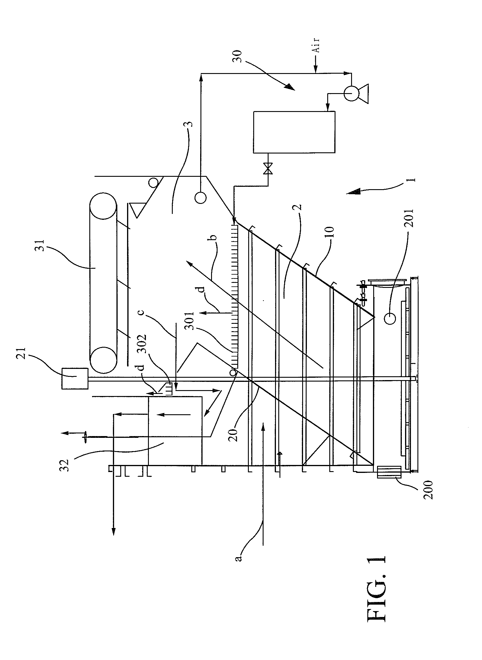
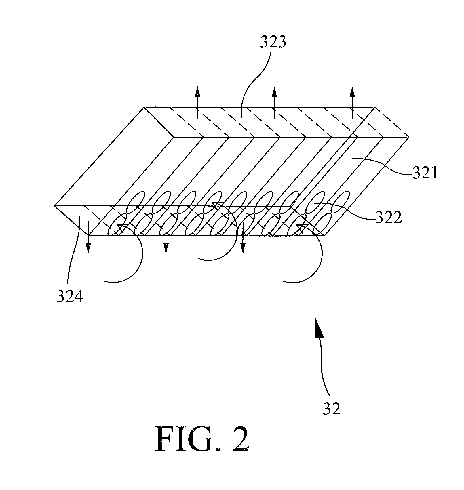
[0046]Referring to FIG. 3, in comparison with the first embodiment, the wastewater treatment tank 1 in accordance with the second preferred embodiment of the present invention is operated in a reverse treatment process. In operation, untreated wastewater flows into the tank body 10 via the wastewater inlet. Firstly, the untreated wastewater passes through the sedimentation treatment unit 32 (as best shown in the direction indicated by a series of arrows c′ in FIG. 3) for preliminary sedimentation treatment.

[0047]Secondly, the wastewater flows to the pressure floatation treatment device 3 (as best shown in the direction indicated by a series of arrows c′ in FIG. 3) for pressure floatation treatment by pressurized water, as best shown in the direction indicated by arrows d in FIG. 3. Thirdly, the wastewater flows downward to the sedimentation treatment device 2 and the heater unit 200 (as best shown in the direction indicated by arrows b′ in FIG. 3) for sedimentation treatment. Finall...

third embodiment

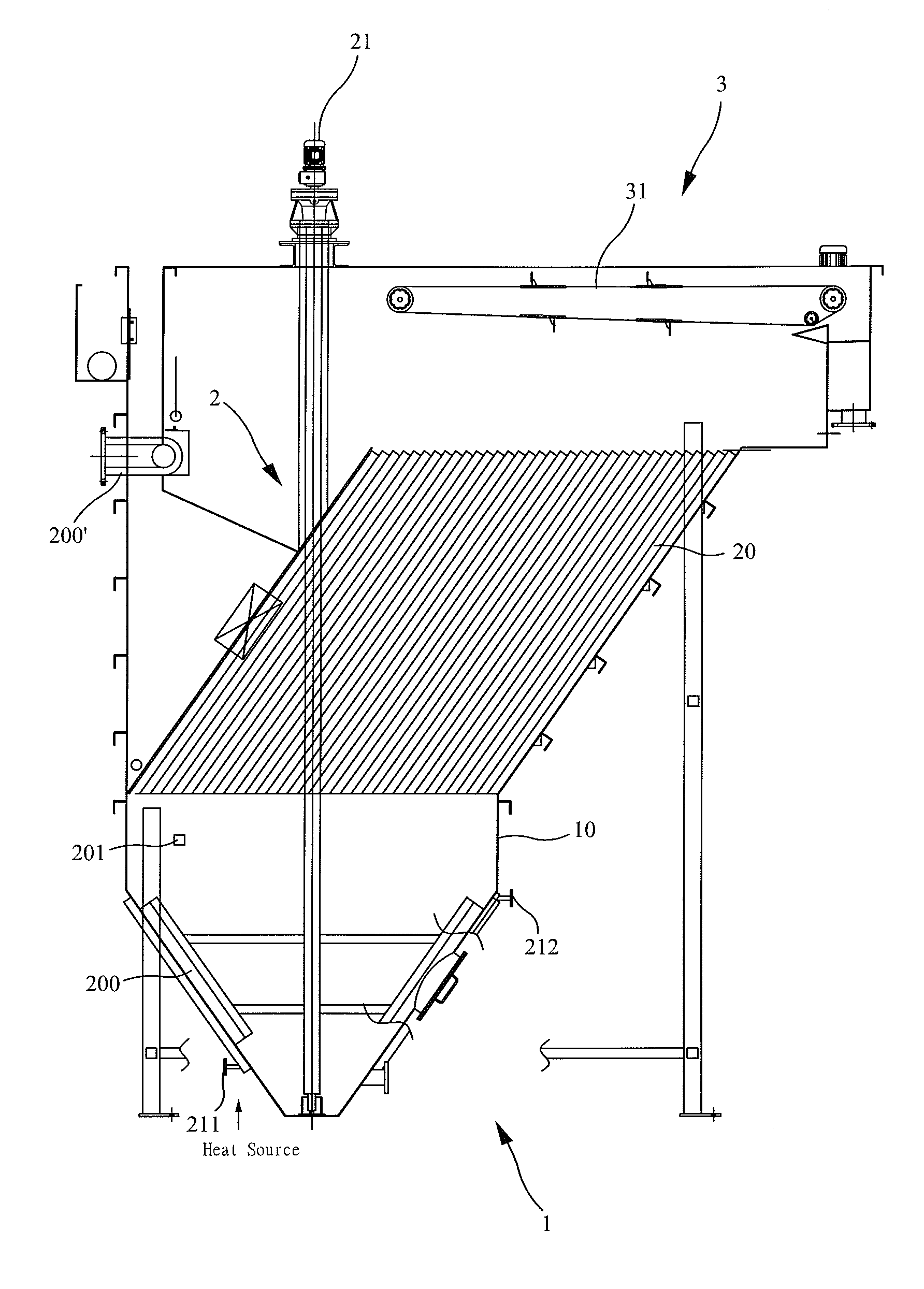
[0050]Referring to FIGS. 4 through 6, the wastewater treatment tank 1 in accordance with the third preferred embodiment of the present invention includes a tank body 10, a sedimentation treatment device 2, at least two heater units 200 and a pressure floatation treatment device 3. In the third embodiment, the heater units 200 are provided at different positions to heat the waste water and the sludge at an upper portion and a lower portion of the tank body 10, for example. By way of example, the heater unit 200 is arranged on an inner wall of the tank body 10 and surrounds the lower portion of the tank body 10. Correspondingly, the heater unit 200′ is selectively arranged on an outer circumferential wall of a pipe line at the upper portion of the tank body 10 adjacent to the pressure floatation treatment device 3 for heating or warming the floated sludge. The heater unit 200 includes a steam inlet 211 and a steam outlet 212 connected with an interior of the heater unit 200. In operat...


PUM

PropertyMeasurementUnit
Temperatureaaaaaaaaaa
Pressureaaaaaaaaaa
Heataaaaaaaaaa

Abstract

A combined sedimentation and pressure floatation wastewater treatment tank includes a tank body, a sedimentation treatment device and a pressure floatation treatment device. The tank body contains a predetermined amount of wastewater for treatment. The sedimentation treatment device is operated to remove relatively heavier sludge from the wastewater by sedimentation treatment, and the pressure floatation treatment device is operated to remove relatively lighter sludge from the initially treated wastewater by pressure floatation treatment. In operation, the wastewater is initially treated by the sedimentation treatment device and is further treated by the pressure floatation treatment device. Alternatively, the wastewater is initially treated by the pressure floatation treatment device and is further treated by the sedimentation treatment device.

Description

CROSS REFERENCE TO RELATED APPLICATIONS[0001]This application is a continuation-in-part of U.S. patent application Ser. No. 12 / 639,066, filed Dec. 16, 2009, which is hereby incorporated by reference in its entirety.BACKGROUND OF THE INVENTION[0002]1. Field of the Invention[0003]The present invention relates to a sedimentation and pressure floatation wastewater treatment device with a heater. More particularly, the present invention relates to a sedimentation arrangement and pressure floatation arrangement incorporated in a single wastewater treatment tank for providing a dual treatment function.[0004]2. Description of the Related Art[0005]In general, wastewater treatment covers several wastewater treatment methods, according to physical properties, for the removal of solid sludge contained in the wastewater. If the sludge is lighter, a pressure floatation method is employed and implemented in a wastewater pressure floatation treatment tank or facilities, for example. If solids and l...

Claims


Application Information

Patent Timeline
IPC IPC(8): C02F1/24C02F1/02B01D35/18
CPCB01D21/24B01D21/0084B03D1/087B03D1/1462B03D1/1468B03D1/1475B03D1/1481C02F1/02C02F1/24C02F2001/007C02F2209/02B03D1/1431B01D21/009B01D21/0045B03D1/082
Inventor TSAI, KUEI-LIN
Owner TSAI KUEI LIN
Why Eureka
Try Eureka