Sheet feeding device and image forming apparatus

a feeding device and a technology for forming apparatus, applied in the direction of transportation and packaging, thin material processing, article separation, etc., can solve the problems of retard rollers with significantly short durability life spans, paper jams, retard rollers with co-rotation failures, etc., to prolong the durability life span of retard rollers and simple structure with ease

Inactive Publication Date: 2012-06-21
CANON KK
View PDF12 Cites 8 Cited by
  • Summary
  • Abstract
  • Description
  • Claims
  • Application Information

AI Technical Summary

Benefits of technology

[0013]According to the invention, it is possible to prolong the durability life span of the retard roller using a simple structure with ease by employing a torque changing unit which changes a rotary torque exerted on the retard roller.

Problems solved by technology

This gives rise to the co-rotation failure of the retard roller.
The co-rotation failure of the retard roller impedes the feeding of the sheet into a nip portion between the feed roller and the retard roller, which is likely to cause a paper jam.
In particular, when the load resistance of the retard roller for separating sheets is heavy and the retard roller is a sponge roller, the problem with that retard roller is a significantly short durability life span compared with general conveying rollers.
However, those sheet feeding devices have the following problems.
That is, in the case of using a plurality torque limiters as in the sheet feeding device disclosed in JP-A No. 2002-2992, the cost of the sheet feeding device increases.

Method used


Image

  • Sheet feeding device and image forming apparatus
  • Sheet feeding device and image forming apparatus
  • Sheet feeding device and image forming apparatus

Examples


first embodiment

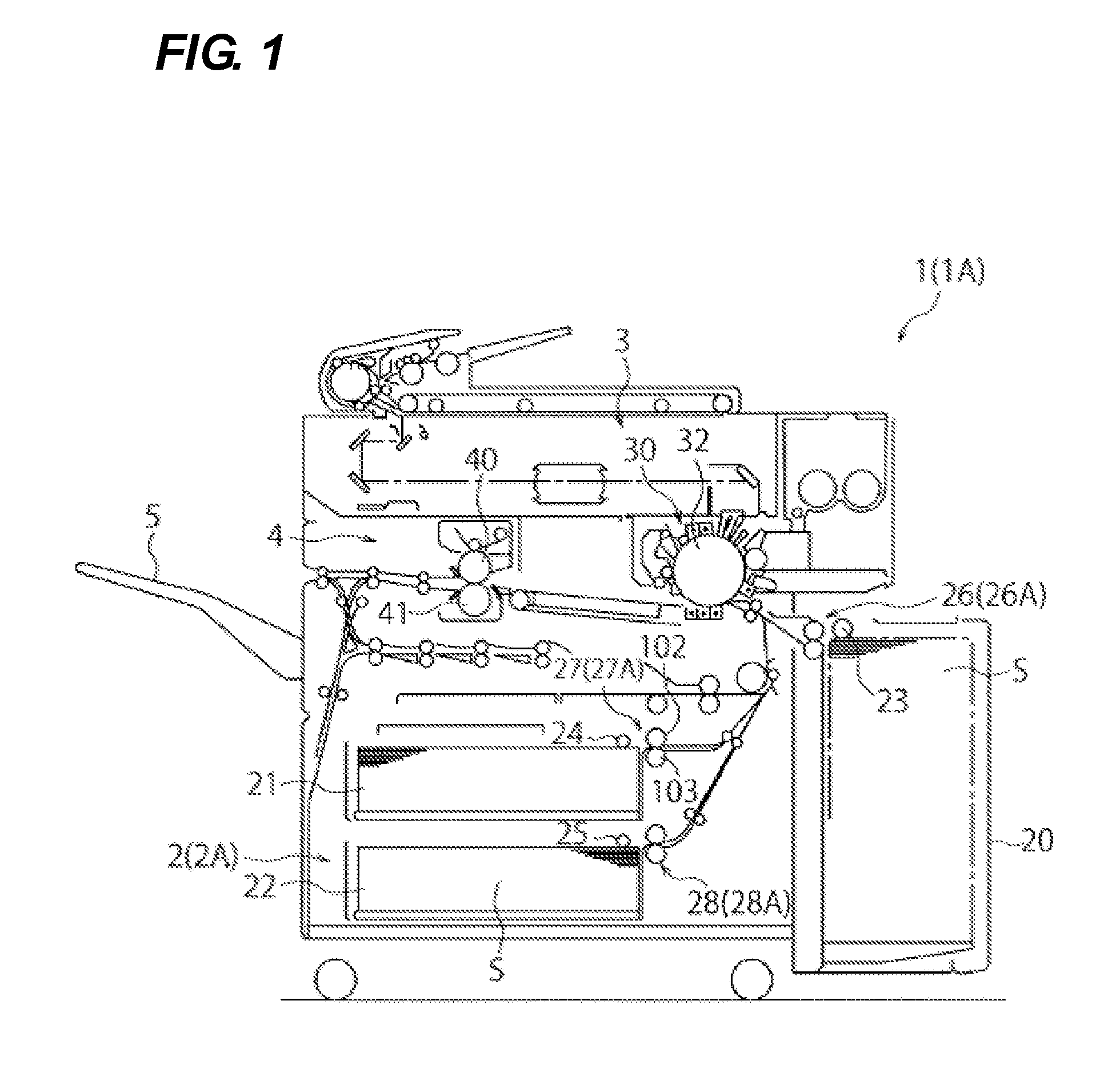
[0021]An image forming apparatus 1 according to a first embodiment of the present invention will be described with reference to the drawings. The overall structure of the image forming apparatus 1 according to the first embodiment will be described first with reference to FIG. 1. FIG. 1 is a cross-sectional view illustrating the overall structure of the image forming apparatus according to an embodiment of the present invention.

[0022]As illustrated in FIG. 1, the image forming apparatus 1 includes a sheet feeding portion 2 which feeds a sheet S, an image forming portion 3 which forms an image on the sheet S, a fixing portion 4 which fixes the image formed on the sheet S, and a discharging portion 5 which discharges the sheet S.

[0023]The sheet feeding portion 2 includes a sheet deck 20, a plurality of universal cassettes 21 and 22, pick-up rollers 23, 24, and 25, separation portions 26, 27, and 28, a pair of pulling-out rollers (not illustrated), and a pair of registration rollers (n...

second embodiment

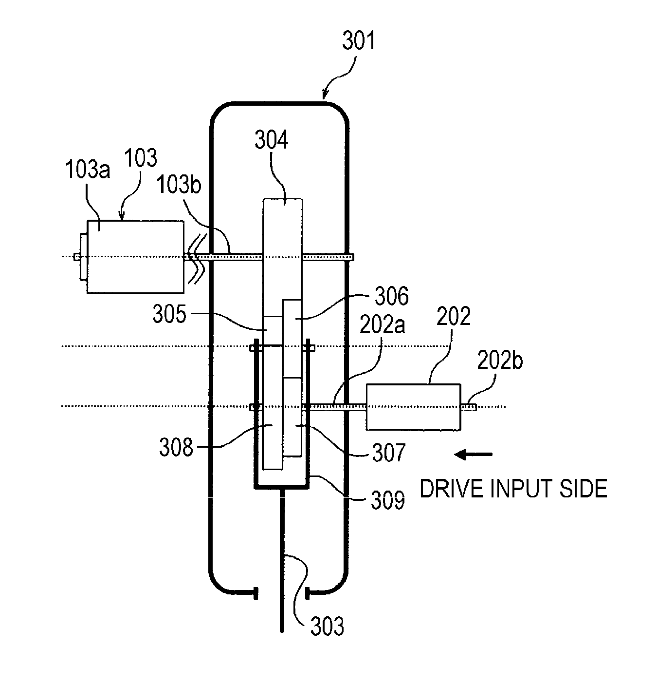
[0056]Next, an image forming apparatus 1A according to a second embodiment of the present invention is described with reference to FIGS. 3A, 3B, 4, and 5 in addition to FIG. 1. FIG. 3A is a plan view illustrating a retard roller 103, a torque limiter 302, and a speed changing device 301 according to the second embodiment. FIG. 3B is a side view illustrating the structure of FIG. 3A. FIG. 4 is a diagram illustrating a detection sensor 402 which detects a collapse amount of a retard roller 103 according to the second embodiment.

[0057]The image forming apparatus 1A according to the second embodiment differs from the first embodiment in terms of separation portions 26A, 27A, and 28A provided in a sheet feeding portion 2A. Specifically, the separation portions 26A, 27A, and 28A include a detection sensor 402 serving as a detection portion. Based on the detection result from the detection sensor 402, an actuator 400 serving as an operation unit operates an operation handle 303. That is, t...


PUM


Abstract

Disclosed is a sheet feeding device capable of prolonging the durability life span of the retard roller with a simple structure with ease and an image forming apparatus which includes the sheet feeding device. The sheet feeding device includes a feed roller 102 which rotates in a sheet feed direction, a retard roller 103 which is able to rotate in a reverse direction to the sheet feed direction which forms a separation nip portion. A torque limiter 202 which is interposed between a drive shaft 202b and a roller shaft 103b of the retard roller 103 to transfer a predetermined torque of the reverse direction to the retard roller 103; and a speed changing device 301 which is interposed between an output shaft 202a of the torque limiter 202 and the roller shaft 103b to change a magnitude of the predetermined torque transferred to the retard roller 103.

Description

BACKGROUND OF THE INVENTION[0001]1. Field of the Invention[0002]The present invention relates to a sheet feeding device and an image forming apparatus, and more particularly to a sheet feeding device which feeds sheets while separating the sheets one by one and an image forming apparatus including the sheet feeding device.[0003]2. Description of the Related Art[0004]In the related art, an image forming apparatus, such as a printer, a copying machine, or a facsimile is equipped with a sheet feeding device which sends a sheet from a sheet stacking portion using a pick-up roller and which separates the sheets one by one using a separation portion and then feeds the separated sheets in a case where multiple sheets are fed.[0005]The separation portion provided in the sheet feeding device is categorized as a roller type which uses a feed roller and a retard roller capable of reverse rotation or a friction separation type which uses a separating member such as a separation roller or a sepa...

Claims


Application Information

Patent Timeline
Patent Type & Authority Applications(United States)
IPC IPC(8): B65H5/06B65H5/12
CPCB65H3/5261B65H2403/732B65H2403/722B65H2403/422
Inventor TAKAHASHI, KAKERU
Owner CANON KK
Why Eureka
Try Eureka