Visual perimeter measurement system and method

a measurement system and perimeter technology, applied in the field of visual perimeter measurement system and method, can solve the problems of difficult use of techniques with small children, system is extremely complicated, and elderly patients suffering from degenerative brain diseases also present the same problems

Inactive Publication Date: 2012-06-21
THE UNIV OF YORK +1
View PDF2 Cites 24 Cited by
  • Summary
  • Abstract
  • Description
  • Claims
  • Application Information

AI Technical Summary

Benefits of technology

[0019]From a yet further aspect another example of the invention provides a peripheral vision measurement system, comprising: a first display device arranged to display a plurality of test images to a test subject at different positions on the display; a processor arranged to control the first display device to display the plurality of test images at the different positions, and to use a determination as to whether the test subject has seen a particular test image at a particular position; wherein the processor is further arranged to calculate the position of an additional test image to be shown to the user at a related position to the particular position of the particular test image in dependence on the determination, the related position being closer to the test subject's line of sight than the particular position, and to control the first display device to display the additional test image at the related position.
[0020]Within one embodiment of the above the related position at which the additional test image is displayed has substantially the same or similar rotational angular position as the first test image, and a smaller angular magnitude. In addition, within one embodiment at least one second test image at a different rotational angular position to the first test image is displayed to the user before the additional test image. With such an arrangement, the test subject does not become aware that test points are being added in to the test, as there is no unusually long gap between the subject perceiving test images.

Problems solved by technology

Such techniques are therefore difficult to use with small children, for example, because small children find the test extremely intimidating, and are unable to maintain visual fixation at the central point in accordance with the test instructions appropriately.
Similarly, elderly patients who may be suffering from degenerative brain diseases also present the same problems.
However, the system is extremely complicated, requiring much space, and equipment to set up.
In addition, the actual criterion by which it is judged whether a target has in fact been seen is open to error, as a decision is made purely based on whether the subject looks towards the direction of the target, but not whether in fact the target has been seen.
This method requires two clinicians, and the movement of the second clinician may be distracting, leading to an inaccurate test.
As such, this method is far from ideal, delivering a potentially poor result, as well as being costly to administer.

Method used


Image

  • Visual perimeter measurement system and method
  • Visual perimeter measurement system and method
  • Visual perimeter measurement system and method

Examples


Embodiment Construction

[0049]Various examples of the invention will now be described with respect to the accompanying figures.

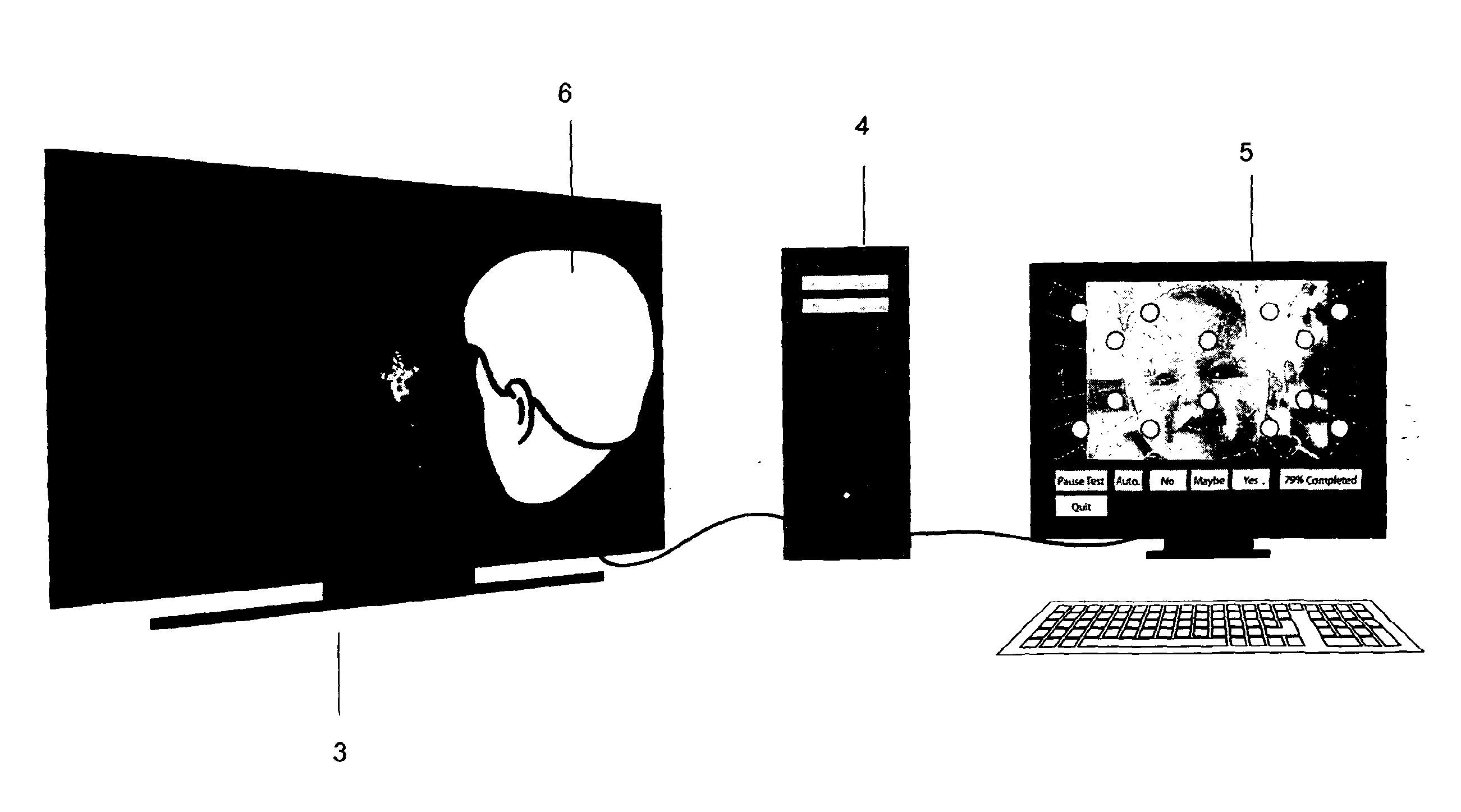
[0050]A first example embodiment of the invention is shown in FIG. 3. Here, a visual perimetry measurement system 10 comprises a patient display screen 3 in front of which a test subject, in this case a small child 6, is positioned. A clinician display screen 5 is also provided. A controlling computer 4 controls the images displayed on both the patient display 3, and the clinician display screen 5. The controlling computer 4 is provided with a suitable software program and corresponding hardware, in order to cause displays to be produce on the patient display screen 3, and the clinician display 5. In addition, the controlling computer 4 also receives feedback from the clinician display screen 5, for example through a mouse or keyboard interface to allow a clinician to select buttons displayed on the clinician display, as will be described. Also provided as part of the system, but n...


PUM


Abstract

In one example of the invention a patient display is provided on which a fixation graphic or video is shown in substantially the centre of the display, and then target graphics or video are shown at different positions on the display about the centre. A test subject is positioned in front of the patient display a known distance therefrom, and a camera captures an image of the test subject's eyes, to allow gaze direction determination to be performed. The captured images are displayed to a clinician user by a controlling test application, the clinician making a determination based on the images as to whether the test subject saw a target graphic or video when it was displayed. The clinician user then makes an appropriate input into the controlling test application, which also logs the position at which the target image was displayed. By displaying target graphics at multiple locations on the screen and logging the clinician inputs, the controlling test application is able to build up a plot of the peripheral vision field of the test subject. This plot can then be graphically displayed to the clinician user, and stored with the test results for future clinical use.

Description

TECHNICAL FIELD[0001]Examples of the present invention relate to a visual perimeter measurement system and method.BACKGROUND TO EXAMPLES OF THE INVENTION [0002]Accurate measurement of peripheral vision in a human can lead to early diagnosis of potentially serious medical conditions. Causes of visual field deficit include neonatal brain haemorrhage or stroke and eye conditions such as retinitis pigmentosa and glaucoma, additionally over 50% of childhood brain tumours present with visual impairment.[0003]A human eye converts light entering it into neural signals which are then sent down the optic nerve. Thus, the left optic nerve carries all of the visual information from the left eye, and the right optic nerve carries all of the visual information from the right eye. The optic nerves meet at the optic chiasm within the brain. Within the optic chiasm nerve fibres carrying visual information from the visual field temporal (lateral) to the vertical mid-line, cross to the other side. The...

Claims


Application Information

Patent Timeline
Patent Type & Authority Applications(United States)
IPC IPC(8): A61B3/024
CPCA61B3/0041A61B3/14A61B3/113A61B3/024G06V40/19
Inventor PELAH, ADARELIZABETH, ALLEN LOUISEEDWARD, SLATER MICHAELROBERT, JACKSON ANDREW
Owner THE UNIV OF YORK
Why Eureka
Try Eureka