
Vacuum processing apparatus and vacuum processing method

Inactive Publication Date: 2012-06-21
ULVAC INC
View PDF16 Cites 7 Cited by
  • Summary
  • Abstract
  • Description
  • Claims
  • Application Information

AI Technical Summary

Benefits of technology

[0029]The present invention is the vacuum processing apparatus including the temperature controlling means for controlling the temperature within the processing chamber to the first temperature-controlled state, in which the processing gases process the surface of the object to be processed, thereby producing a reaction product, and to the second temperature-controlled state in which the resulting reaction product is sublimated and removed, wherein in the second temperature-controlled state in which the resulting reaction product is sublimated and removed, the inert gas

Problems solved by technology

In accordance with demands for the mass production and cost reduction of semiconductor devices in recent years, it is required to carry out the above-mentioned processing with efficiency and at a low cost in a vacuum apparatus for the processin

Method used


Image

  • Vacuum processing apparatus and vacuum processing method
  • Vacuum processing apparatus and vacuum processing method
  • Vacuum processing apparatus and vacuum processing method

Examples


Example

TEST EXAMPLE

[0088]Using the vacuum processing apparatus according to the first embodiment, the first gas introducing paths 11 were renewed, and then batch processing of the silicon substrate was repeated for about 100 batches. Particles formed were counted, and the results are shown in FIG. 12(a). The particle count was made by sampling 3 of about 50 silicon substrates per batch processing, and counting the number of 0.2 μm or larger particles observed on each silicon substrate. The 3 silicon substrates are indicated by ▴, ▪ and ♦.

[0089]With the processing of FIG. 12(a), in the second step of etching, the first gas introducing means was allowed to function as the inert gas introducing means, and only N2 gas was introduced at a flow rate of 2.0 L / min, with the plasma generating section 16 being stopped and the supply of NH3 gas being stopped. By so doing, the sublimate was prevented from passing through the first gas introducing ports 12 and diffusing into the first shower nozzle 13 ...


PUM

PropertyMeasurementUnit
Thicknessaaaaaaaaaa

Abstract

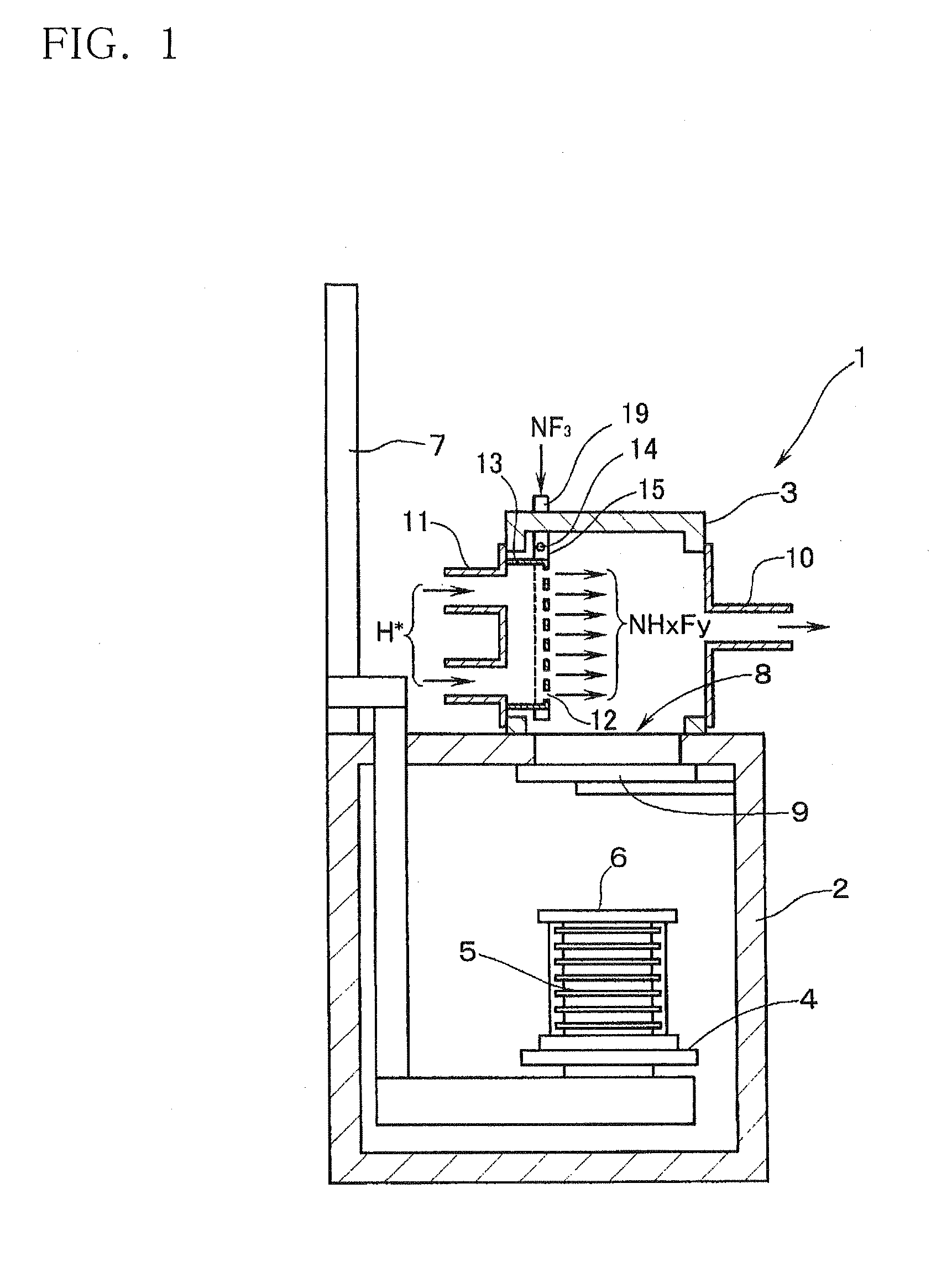
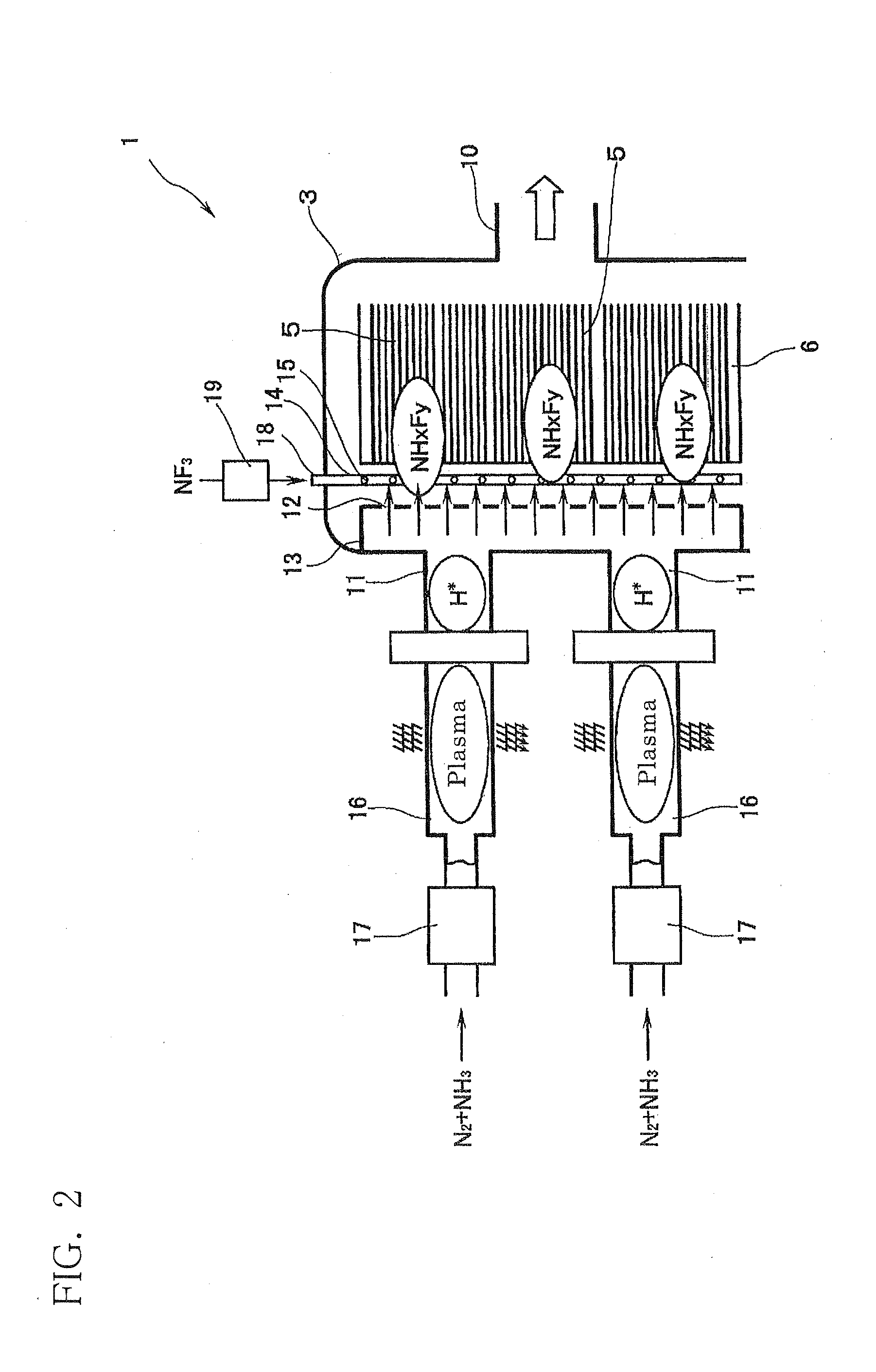
A vacuum processing apparatus, comprising: a processing chamber 3 in which an object to be processed is placed and a predetermined vacuum state is formed; a first processing gas introducing means 12 for converting a first processing gas into a radical state and introducing the resulting first processing gas in the radical state into the processing chamber through first processing gas introducing ports which open to the interior of the processing chamber; a second processing gas introducing means 15 for introducing a second processing gas, which is reactive with the first processing gas in the radical state, into the processing chamber through second processing gas introducing ports which open to the interior of the processing chamber; a temperature controlling means for controlling the temperature within the processing chamber 3 to a first temperature-controlled state, in which the first processing gas in the radical state and the second processing gas process the surface of the object to be processed, thereby producing a reaction product, and to a second temperature-controlled state in which the resulting reaction product is sublimated and removed; and an inert gas introducing means for introducing an inert gas into the processing chamber 3 through the processing gas introducing ports 12 when the temperature controlling means controls the temperature within the processing chamber to the second temperature-controlled state.

Description

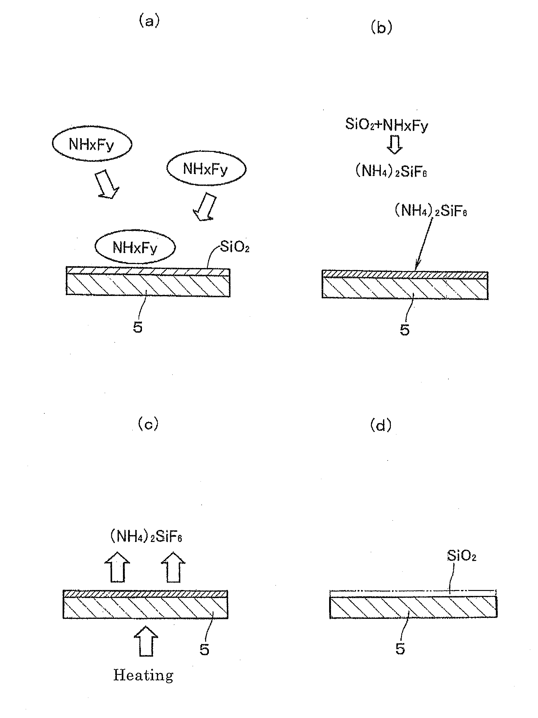
TECHNICAL FIELD[0001]This invention relates to a vacuum processing apparatus and a vacuum processing method for performing processing, for example, etching, in a processing chamber in a vacuum state.PRIOR ART[0002]In a process for producing a semiconductor device, it is necessary, for example, to remove a native oxide film (e.g., SiO2) formed on a wafer at the bottom of a contact hole of a semiconductor substrate (semiconductor wafer). As a technology for removing the native oxide film, various proposals using hydrogen in a radical state (H*) and NF3 gas have been made (see, for example, Patent Document 1).[0003]The technology disclosed in Patent Document 1 is a technology which comprises introducing gases through a first nozzle portion for introducing H gas, which has been converted into radicals by a plasma using microwaves, and through second nozzle portions for introducing NF3, in a first gas introducing section within a processing chamber brought to a predetermined vacuum state...

Claims


Application Information

Patent Timeline
IPC IPC(8): H01L21/306H01L21/3065
CPCH01J37/32357H01J37/32422H01J37/3244H01L21/76814H01L21/02046H01L21/02063H01J37/32449H01L21/3065H05H1/24
Inventor ONO, YOUHEIKAWANA, MASAAKIMIURA, YUTAKA
Owner ULVAC INC
Learn More