
Systems and Methods For Small Bore Aspiration

Active Publication Date: 2012-06-21
ALCON INC
View PDF4 Cites 31 Cited by
  • Summary
  • Abstract
  • Description
  • Claims
  • Application Information

AI Technical Summary

Benefits of technology

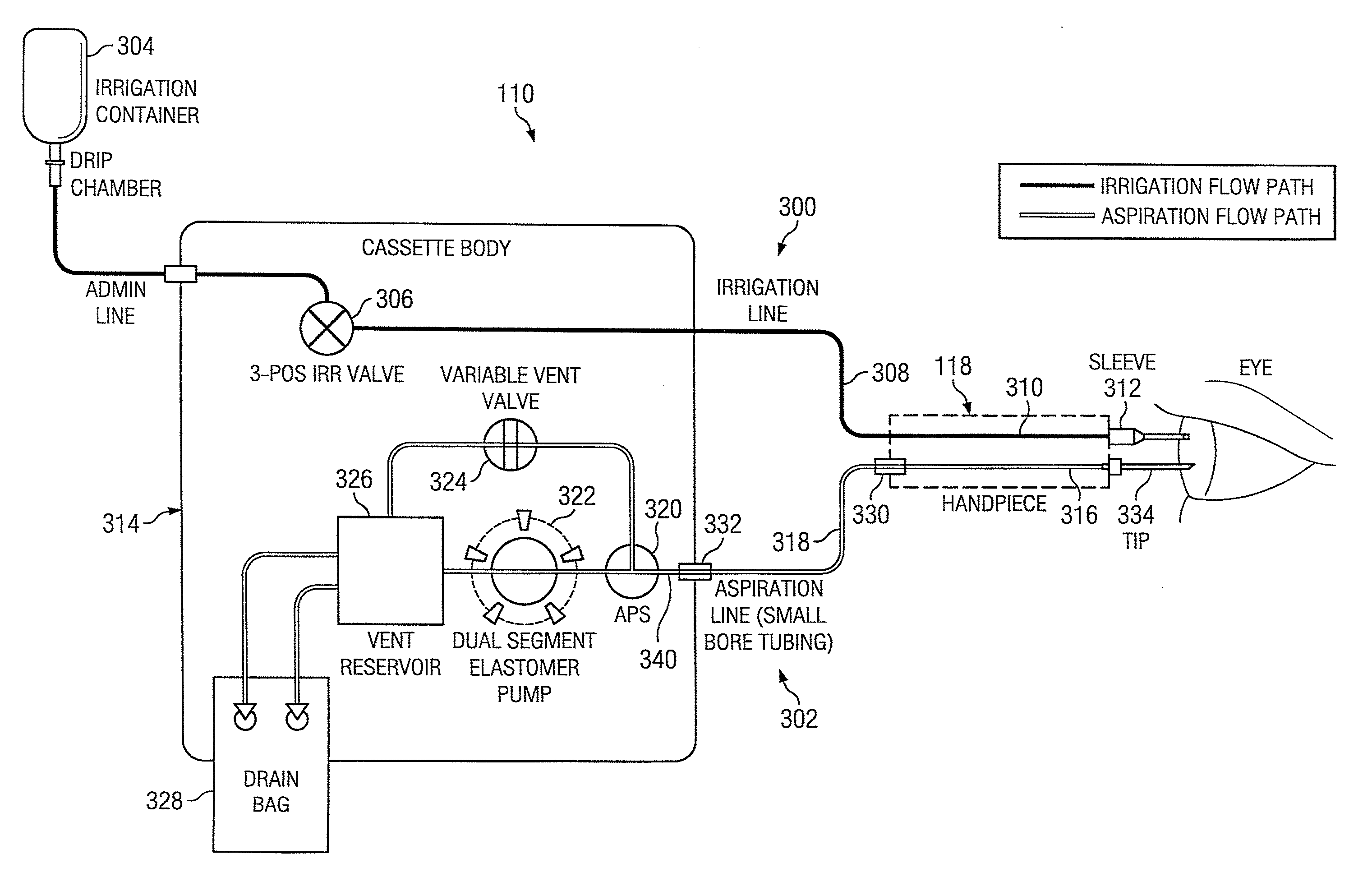
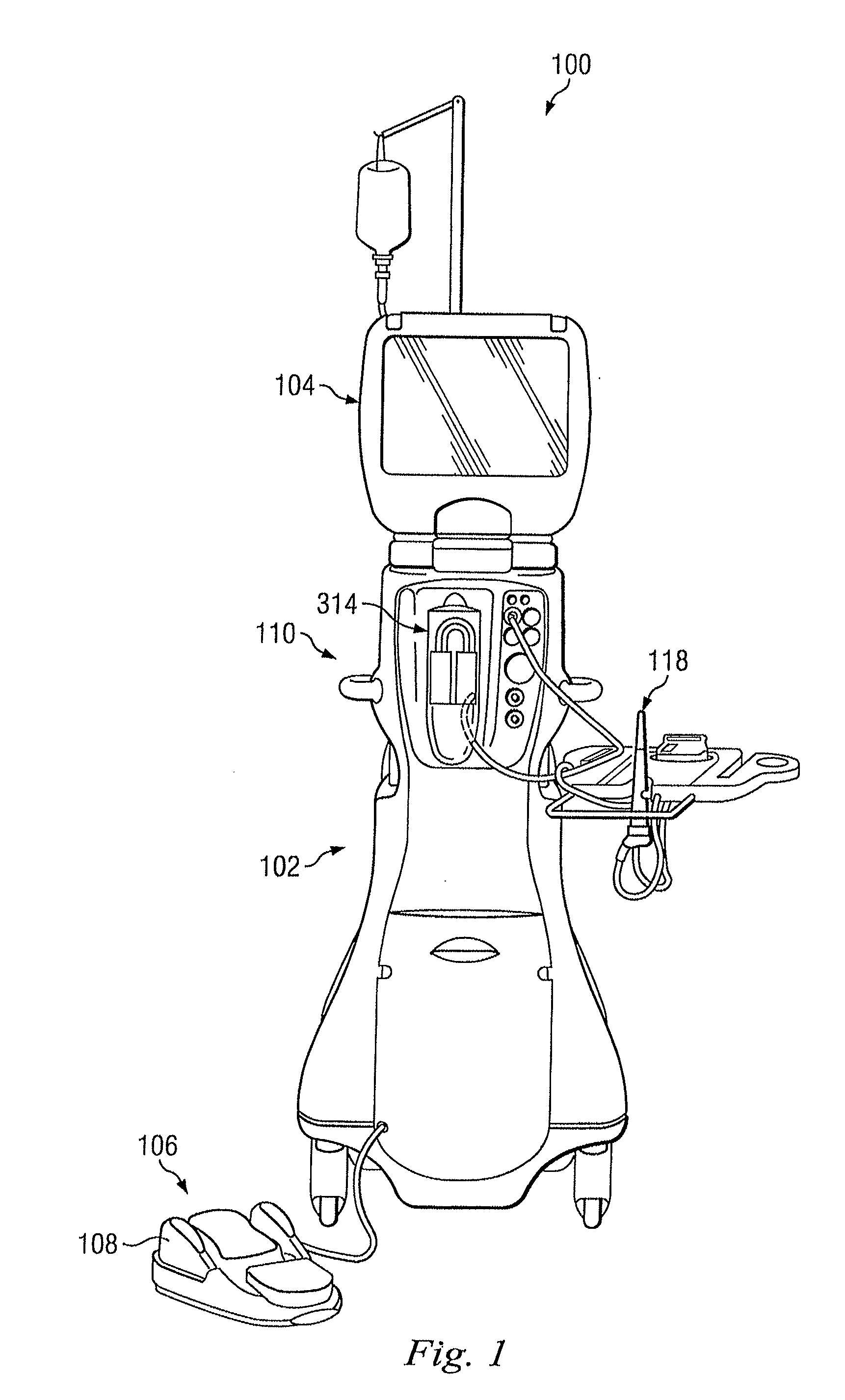
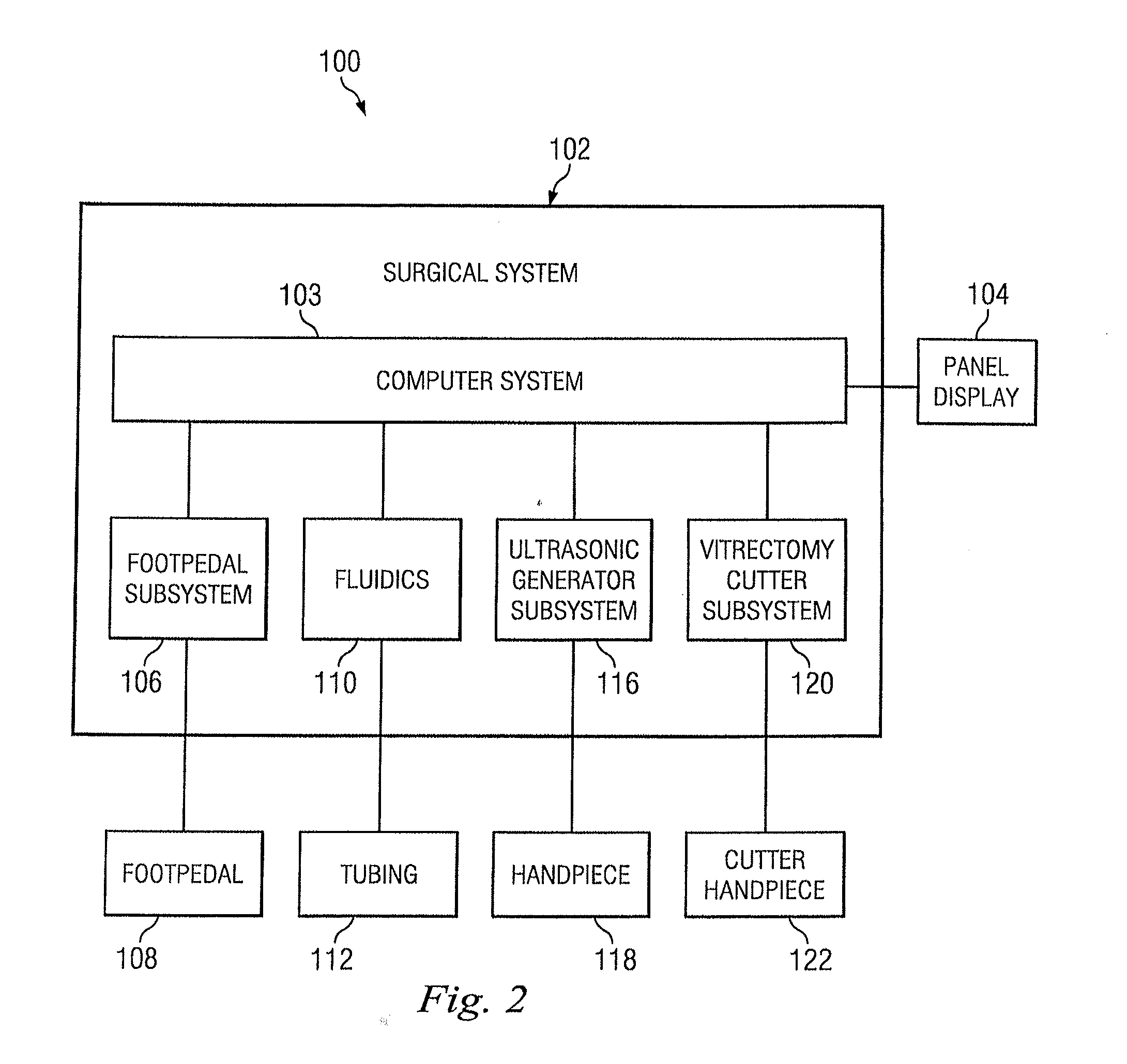
[0011]In one exemplary aspect, the present disclosure is directed to an assembly for a phacoemulsification surgical system. The assembly includes a phacoemulsification hand piece configured to deliver irrigating fluid to a surgical site. The phacoemulsification hand piece includes an ultrasonic tip having a lumen sized and configured to aspirate aspirating fluid from the surgical site. The assembly also includes an irrigation system arranged to provide the irrigating fluid to the phacoemulsification hand piece to irrigate the surgical site and includes an aspiration system arranged to aspirate the aspirating fluid from the surgical site. The aspiration system includes an aspiration path within the phacoemulsification hand piece. The aspiration path extends from the ultrasonic tip and is arranged and configured to permit flow of the aspirating fluid through the hand piece. The aspiration system also includes a flexible small bore aspiration tubing in fluid communication with the aspiration path. The small bore aspiration tubing has a nominal inner diameter smaller than about 0.050 inch (other diameters are also contemplated) to reduce levels of occlusion surge within the surgical system. The inner diameter is substantially consistent through the length of the small bore aspiration tubing. A high-output, peristaltic pump communicates with the small bore aspiration tubing and is operable to create a flow of about 60 cc / min. through the small bore aspiration tubing.
[0013]In another exemplary aspect, the present disclosure is directed to a small bore aspiration system arranged to receive aspiration fluid from an ultrasonic tip used in a phacoemulsification surgical assembly. The system includes an aspiration path within the phacoemulsification hand piece that extends from the ultrasonic tip and is arranged and configured to permit flow of the aspirating fluid through the hand piece. It also includes a flexible small bore aspiration tubing in fluid communication with the aspiration path. The small bore aspiration tubing has a nominal inner diameter smaller than about 0.050 inch (other diameters are also contemplated) to reduce levels of occlusion surge within the surgical system, and the inner diameter being substantially consistent through the length of the small bore aspiration tubing. The system also includes a high-output, peristaltic pump in communication with the small bore aspiration tubing.

Problems solved by technology

While a consistent fluid pressure in the eye is desirable during the phacoemulsification procedure, common occurrences or complications create fluctuations or abrupt changes in fluid flow and pressure at the eye.
One known cause for these is occlusions or flow obstructions that block the needle tip.
This common, and sometimes desirable occurrence, results in a sharp increase in vacuum in the aspirating line.
When the occlusion is removed, the resulting high demand for fluid from the eye to relieve the vacuum can cause a sudden shallowing of the anterior chamber, as the aspiration flow momentarily sharply increases over the irrigation flow.
While such a reduced area reduces the effects of occlusion surge, reduction of aspiration path cross-section can also increase the potential for clogging during the procedure.
However, the effectiveness of these solutions is limited due to the relatively large tubing compliance between the resistive element and the eye.
This solution of adding flexible tubing length has the undesirable effect of adding additional compliance to the aspiration path.
Methods with small bore aspiration lines, such as lines with a diameter of 0.050 inches or less, have generally been avoided because small bore lines may become easily clogged, potentially creating inconsistent flow rates, resulting in high levels of occlusion surge, and possibly resulting in undesirable levels of trauma during the surgical procedure.
In addition, methods with small bore aspiration lines have generally been avoided because, as a result of the small bore with increased wall resistance, pumping that achieves a desirable flow rate can be difficult.

Method used


Image

  • Systems and Methods For Small Bore Aspiration
  • Systems and Methods For Small Bore Aspiration
  • Systems and Methods For Small Bore Aspiration

Examples


Embodiment Construction

[0026]Reference is now made in detail to several exemplary embodiments, examples of which are illustrated in the accompanying drawings. Wherever possible, the same reference numbers are used throughout the drawings to refer to the same or like parts.

[0027]This disclosure is directed to an aspiration system that may achieve lower levels of occlusion surge than currently known systems under similar conditions. These lower levels derive from a novel, small bore aspiration line that provides increased fluid resistance when compared to known systems. This increased fluid resistance dampens or reduces the levels of occlusion surge in the aspiration line, potentially resulting in more stable and predictable surgical processes.

[0028]The small bore aspiration tubing decreases occlusion surge levels in at least two ways. First, the smaller diameter of the small bore fluid path introduces a greater level of wall resistance than larger bore fluid paths. This wall resistance decreases the amount...


PUM


Abstract

An assembly for a phacoemulsification surgical system includes an aspiration system arranged to aspirate fluid from a surgical site. The aspiration system includes an aspiration path within the phacoemulsification hand piece and includes a flexible small bore aspiration tubing in fluid communication with the aspiration path. The small bore aspiration tubing has a nominal inner diameter smaller than about 0.050 inch to reduce levels of occlusion surge within the surgical system. A high-output, peristaltic pump communicates with the small bore aspiration tubing and is operable to create a flow through the small bore aspiration tubing.

Description

PRIORITY CLAIM [0001]This application claims the benefit of priority of U.S. Provisional Patent Application Ser. No. 61 / 423,752 titled “Small Bore Aspiration System”, filed on Dec. 16, 2010, whose inventors are Gary P. Sorensen and Eric Lee.BACKGROUND OF THE INVENTION[0002]The present invention relates to aspiration systems used in phacoemulsification procedures, and more particularly, to aspirations systems employing small bore elements to improve operation.[0003]Typical surgical instruments suitable for phacoemulsification procedures on cataractous lenses include an ultrasonically driven phacoemulsification hand piece with a cutting needle and an irrigation sleeve, and a control console. The hand piece is attached to the control console by an electric cable and flexible tubing. The flexible tubing supplies irrigation fluid to the surgical site and carries aspiration fluid from the surgical site to a waste or discard reservoir.[0004]During a phacoemulsification procedure, the tip o...

Claims


Application Information

Patent Timeline
IPC IPC(8): A61F9/007
CPCA61F9/00745A61M1/0058A61F9/00763A61M1/84A61M1/77A61F9/00736
Inventor SORENSEN, GARY P.LEE, ERIC
Owner ALCON INC
Learn More