Reduced Friction Vitrectomy Probe

a technology of vitrectomy and friction, applied in the field of vitrectomy probes, can solve the problems of affecting the efficiency and performance of the vitrectomy probe, affecting the cutting rate, and the difficulty of vitrectomy base dissection, and friction may affect or even limit the achievable cut ra

Active Publication Date: 2012-06-21
ALCON INC
View PDF13 Cites 14 Cited by
  • Summary
  • Abstract
  • Description
  • Claims
  • Application Information

AI Technical Summary

Benefits of technology

[0011]In another exemplary aspect, the present disclosure is directed to a vitrectomy probe including a housing, a fluidic motor disposed within the housing, a needle extending from the housing, and a cutter assembly. The cutter assembly includes an inner cutting member disposed within and axially moveable relative to the needle, a drive shaft disposed within the housing and axially moveable relative to the housing, and a coupler disposed within the housing coupling the drive shaft and the inner cutting member. The motor is associated with the drive shaft in a manner that drives the cutter assembly in an oscillating manner. The probe also includes a total of two seals within the housing in contact with the cutter assembly for sealing against fluid leakage. The two seals include a first seal and a second seal each sealing about the cutter assembly. The first seal is disposed in fluid communication with at least one air port and prevents fluid flow along the cutter assembly. The second seal is disposed in fluid communication with the aspiration pressure to prevent air flow past the second seal and into aspiration fluid flow.
[0012]In another exemplary aspect the present disclosure is directed to a method of manufacturing a vitrectomy probe. The method includes disposing a motor within a housing, disposing a needle to extend from the housing. It also includes assembling a cutter assembly. Assembling the cutter assembly includes the steps of inserting an inner cutting member within the needle in a manner that the inner cutting member is movable relative to the needle, placing a drive shaft within the housing in a manner that the drive shaft is axially moveable relative to the housing, and coupling the drive shaft and the inner cutting member with a coupler. The motor and the drive shaft are associated in a manner that the motor drives the cutter assembly in an oscillating manner. Two or fewer seals are provided within the housing in contact with the cutter assembly for sealing against fluid leakage. This includes steps of sealing about the cutter assembly with a first seal, the first seal being disposed in fluid communication with at least one air port and prevents fluid flow along the cutter assembly, and sealing about the cutter assembly with a second seal, the second seal being disposed in fluid communication with the aspiration pressure to prevent air flow past the second seal and into aspiration fluid flow.

Problems solved by technology

Therefore, cutting and removing the vitreous must be done with great care to avoid traction on the retina, the separation of the retina from the choroid, a retinal tear, or, in the worst case, cutting and removal of the retina itself In particular, delicate operations such as mobile tissue management (e.g. cutting and removal of vitreous near a detached portion of the retina or a retinal tear), vitreous base dissection, and cutting and removal of membranes are particularly difficult.
Since vitrectomy probes operate by axial oscillation of one cutting member relative to the other, friction generated by or applied against the oscillating components can affect the efficiency and the performance of the vitrectomy probe.
For example, friction may affect or even limit the achievable cut rates with a particular vitrectomy probe.
Friction results from a number of factors, including contact points between moving and fixed components within the probe.

Method used


Image

  • Reduced Friction Vitrectomy Probe
  • Reduced Friction Vitrectomy Probe
  • Reduced Friction Vitrectomy Probe

Examples


Embodiment Construction

[0022]Reference is now made in detail to the exemplary embodiments, examples of which are illustrated in the accompanying drawings. Wherever possible, the same reference numbers are used throughout the drawings to refer to the same or like parts.

[0023]The vitrectomy probes and methods described herein are designed to have relatively increased performance levels by including structural arrangements and designs that reduce the overall area of contact of oscillating cutting members, thereby decreasing friction levels when compared to the known probes.

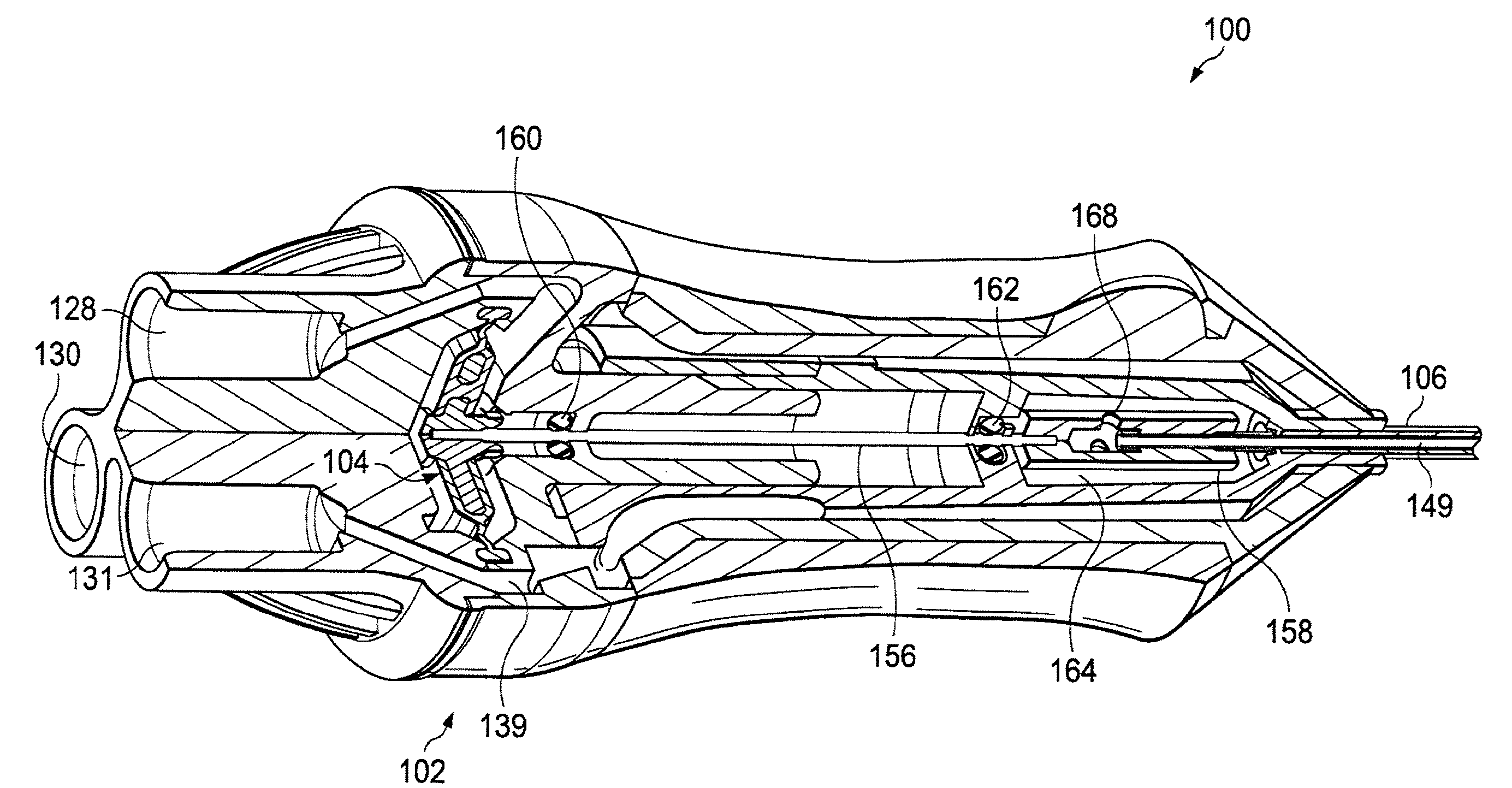
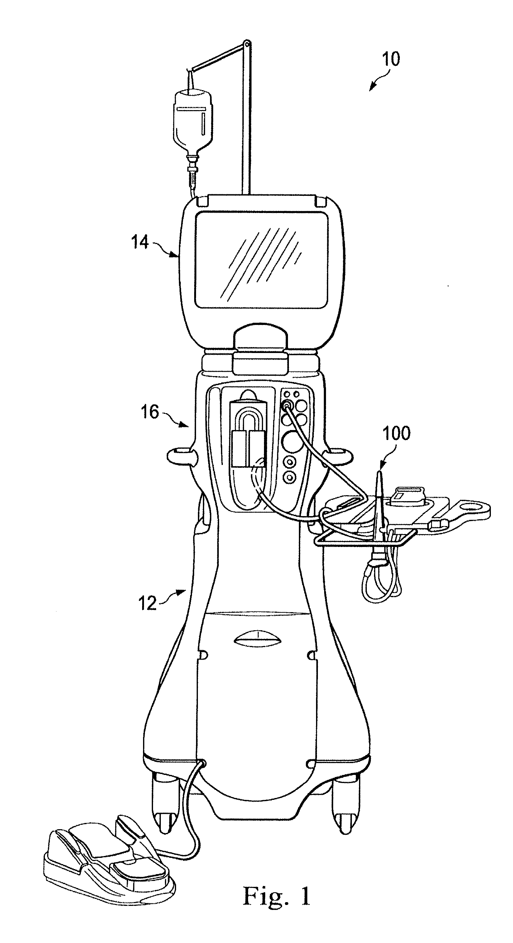
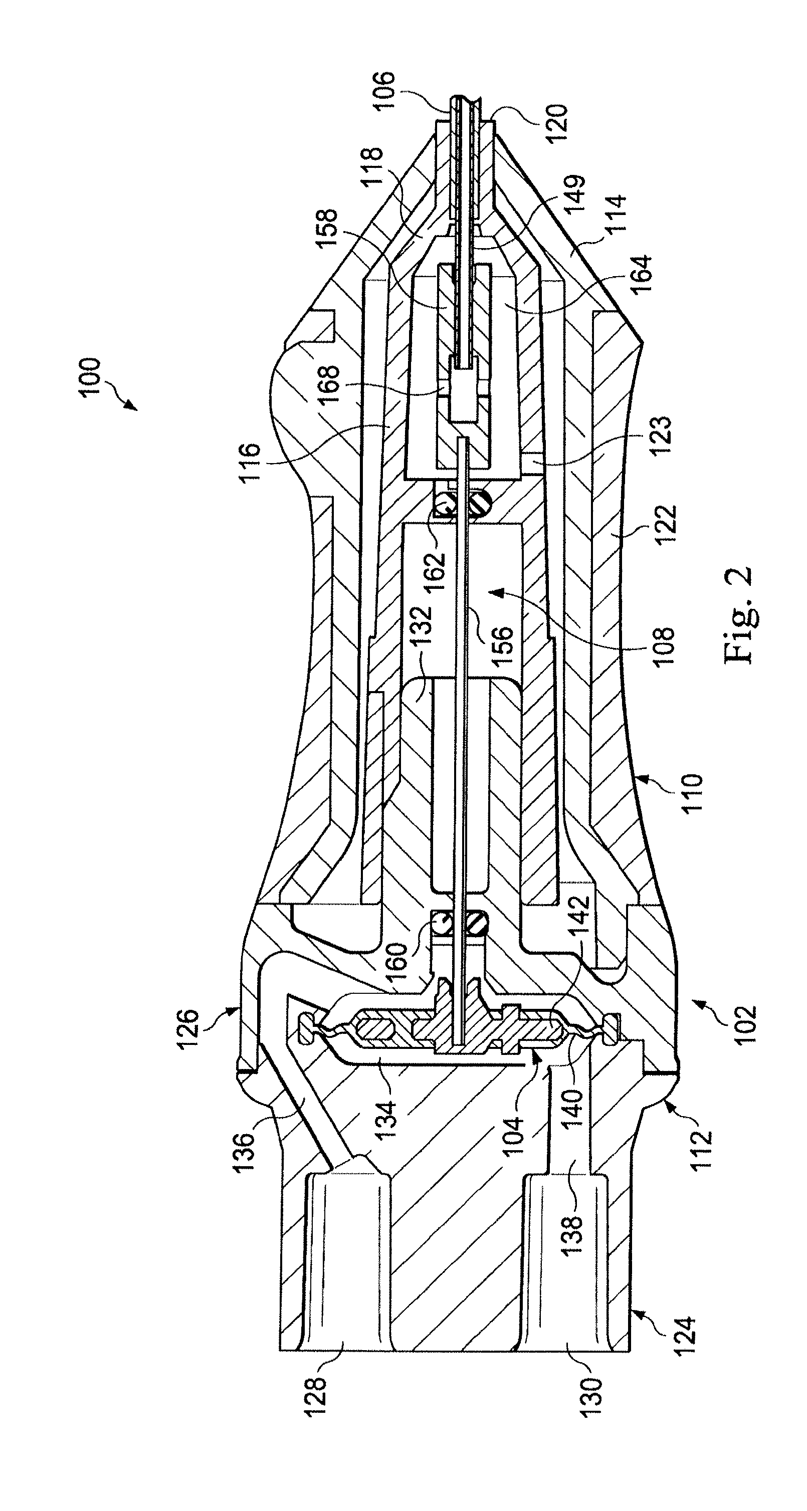
[0024]FIG. 1 illustrates a vitrectomy surgical machine, generally designated 10, according to an exemplary embodiment. The machine 10 includes a base housing 12 and an associated display screen 14 showing data relating to system operation and performance during a vitrectomy surgical procedure. The machine 10 includes a vitrectomy cutter system 16 that includes, among other elements, a vitrectomy cutter 100, a power driving unit, such as a ...


PUM


Abstract

A vitrectomy probe includes a housing, a fluidic motor disposed within the housing, a needle extending from the housing, and a cutter assembly. The cutter assembly includes an inner cutting member disposed within and axially moveable relative to the needle, a drive shaft disposed within the housing and axially moveable relative to the housing, and a coupler disposed within the housing coupling the drive shaft and the inner cutting member. The motor is associated with the drive shaft in a manner that drives the cutter assembly in an oscillating manner. The probe also includes two or fewer seals within the housing in contact with the cutter assembly for sealing against fluid leakage.

Description

PRIORITY CLAIM[0001]This application claims the benefit of priority of U.S. Provisional Patent Application Ser. No. 61 / 423,151 titled “Reduced Friction Vitrectomy Probe”, filed on Dec. 15, 2010, whose inventor is Brian William McDonell, which is hereby incorporated by reference in its entirety as though fully and completely set forth herein.BACKGROUND OF THE INVENTION[0002]The present invention relates to vitrectomy probes and more particularly, to vitrectomy probes structurally arranged to operate with a reduced level of friction.[0003]Microsurgical procedures frequently require precision cutting and / or removing various body tissues. For example, certain ophthalmic surgical procedures require cutting and removing portions of the vitreous humor, a transparent jelly-like material that fills the posterior segment of the eye. The vitreous humor, or vitreous, is composed of numerous microscopic fibrils that are often attached to the retina. Therefore, cutting and removing the vitreous m...

Claims


Application Information

Patent Timeline
Patent Type & Authority Applications(United States)
IPC IPC(8): A61F9/00
CPCA61F9/00763
Inventor MCDONELL, BRIAN WILLIAM
Owner ALCON INC
Why Eureka
Try Eureka