
Tactical smart grids

Active Publication Date: 2012-06-21
PALO ALTO RES CENT INC
View PDF28 Cites 20 Cited by
  • Summary
  • Abstract
  • Description
  • Claims
  • Application Information

AI Technical Summary

Benefits of technology

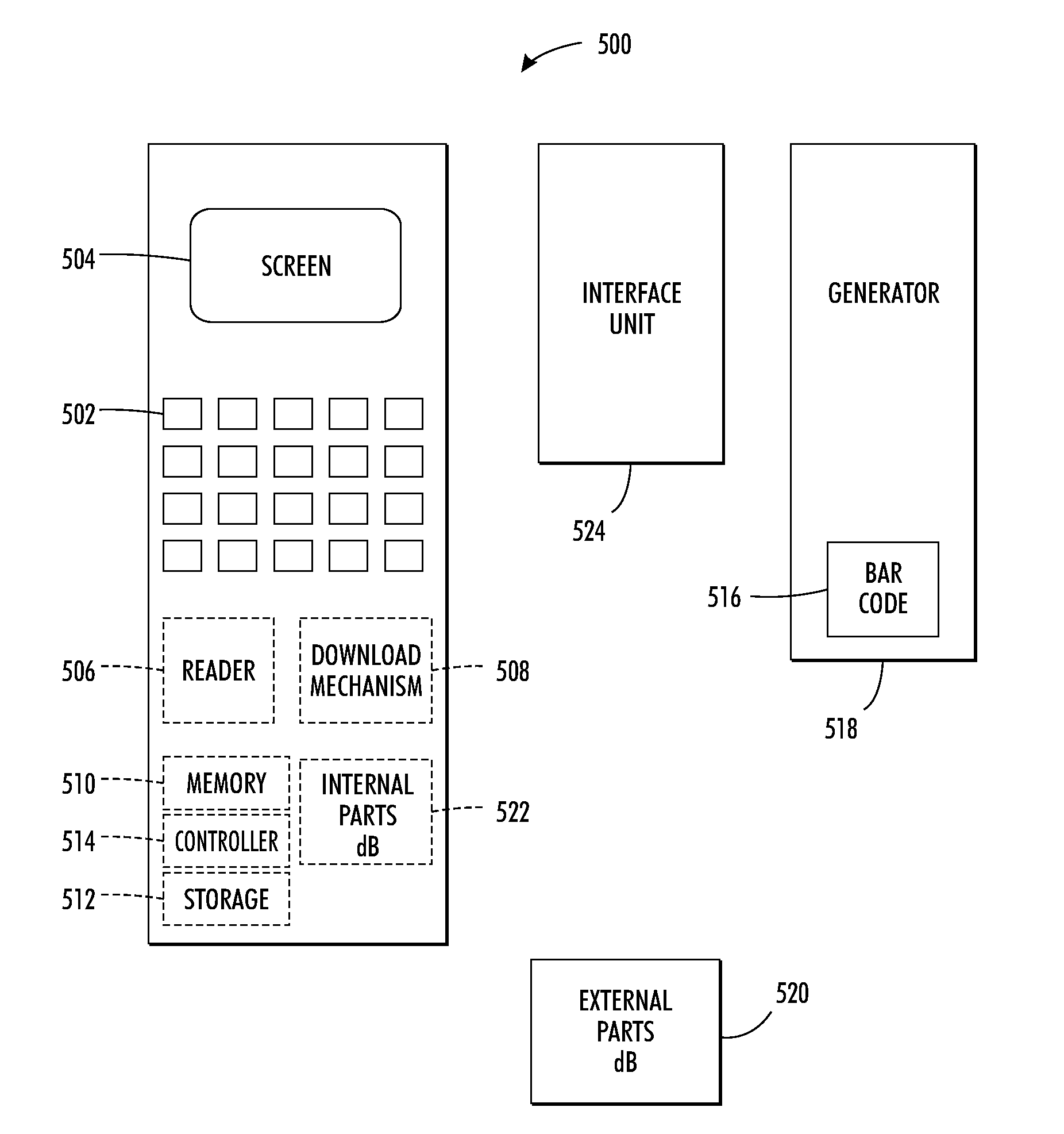
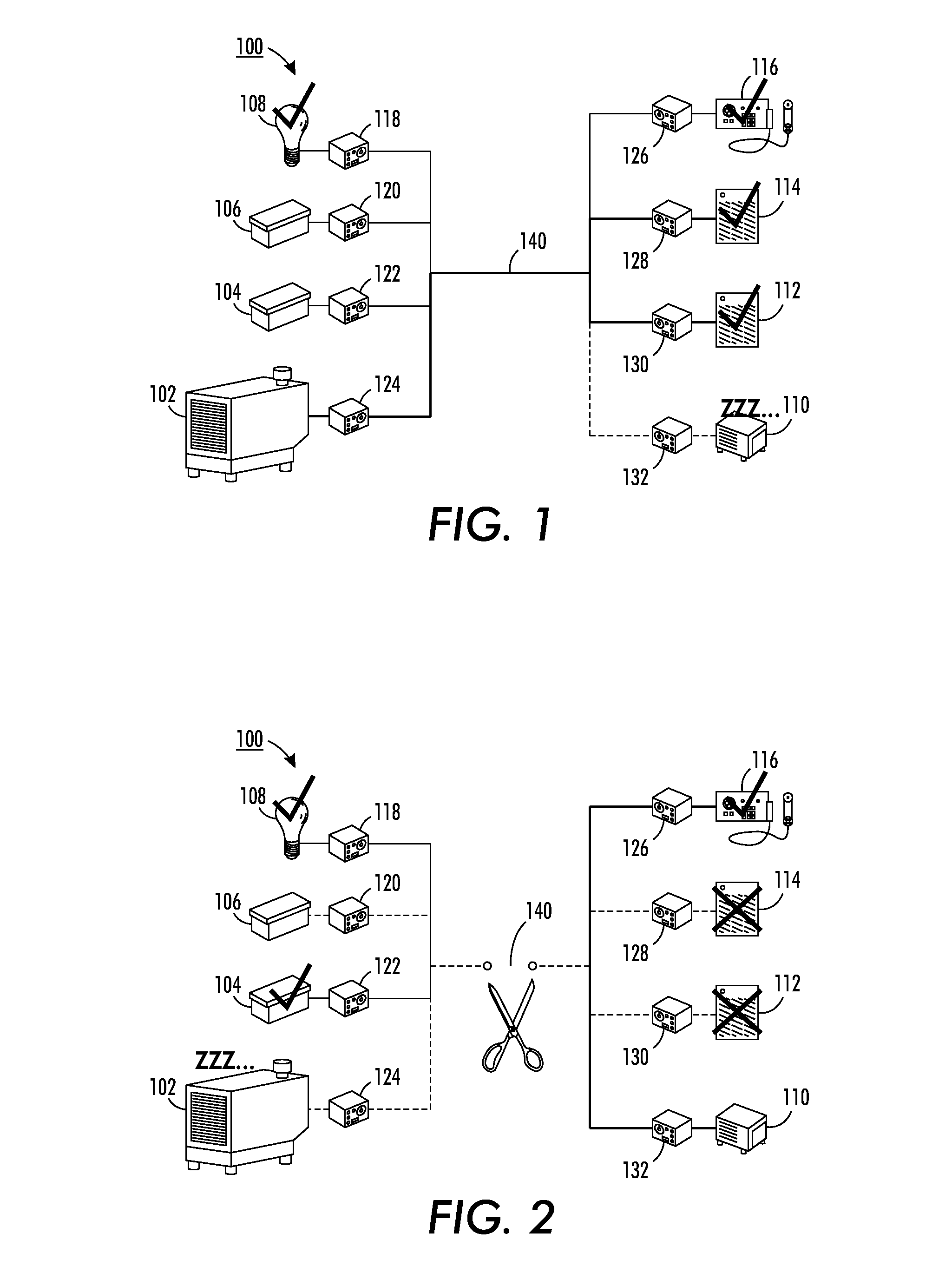
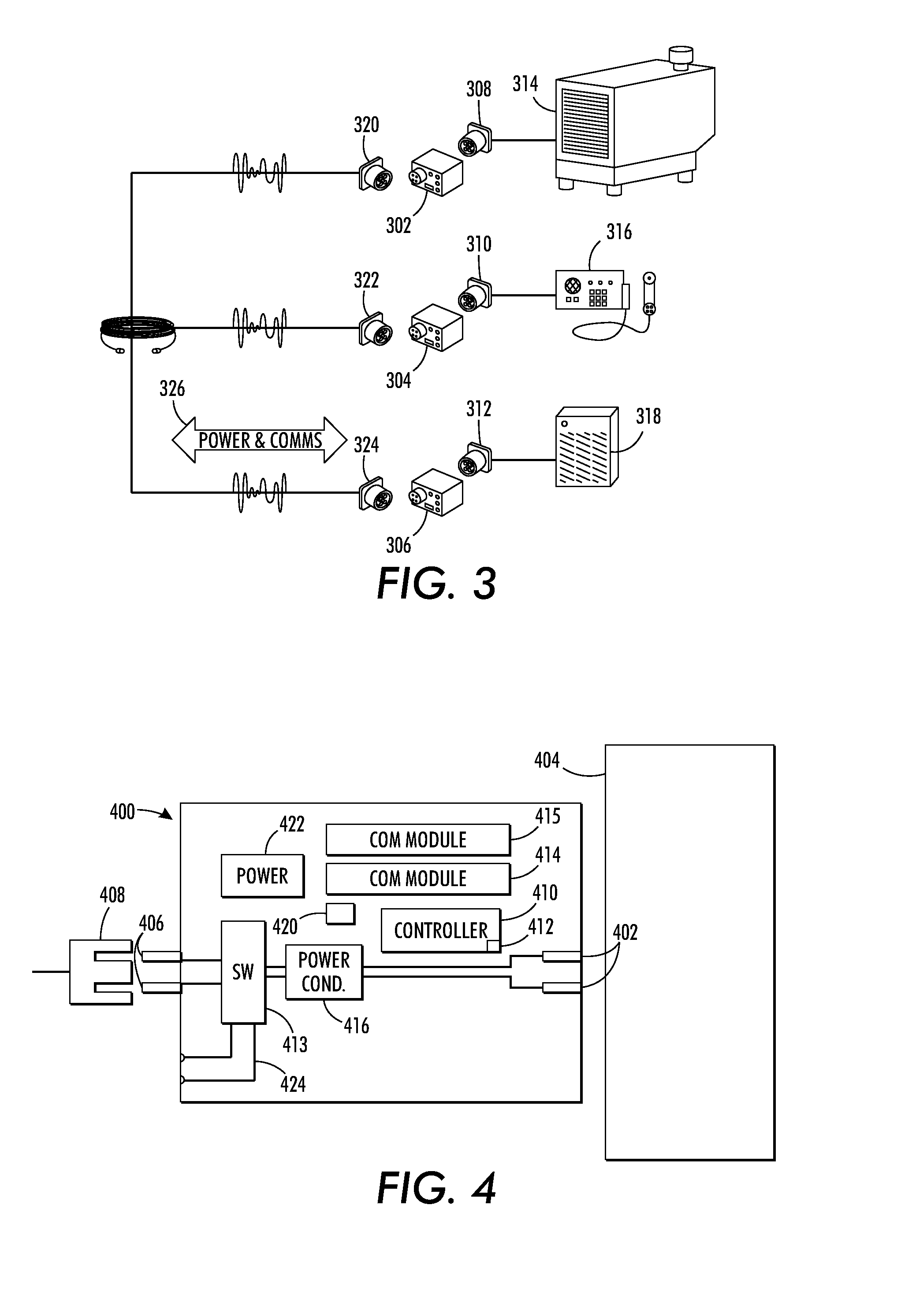
[0009]A tactical smart grid system and method includes a plurality of energy generators and a plurality of loads, where the loads require energy from at least some of the energy generators. A plurality of interface units are provided, where each energy generator and load are connected to one of the plurality of interface units. Each of the interface units including a controller to thereby provide distributed intelligence and distributed system control, thereby removing the requirement of a centrally controlled system.

Problems solved by technology

Also due to the size of the systems or networks involved, the elements being supplied with the energy (e.g., homes), the energy generators (e.g. power plants) and the energy controlling infrastructure (e.g., the components that bring intelligence to the system or network) are cumbersome and not easily moved from one physical location to another.
If any single generator fails, then all loads relying upon that generator are unexpectedly powered down until a replacement generator is brought in, or repairs effected.
Further, due to this isolation at any given time, most generators will be running only partly loaded—this wastes fuel since peak fuel efficiency is when the generators are operated near their maximum rated load.
However centralized control in small or micro environments is impractical.
For example, systems employing centralized control often require large pieces of equipment, some being large enough that they need to be trailer-mounted systems.
So in environments focused of a small number of people (about 2-200) it may not be practical to bring large pieces of equipment just to make generators somewhat more efficient.
Such central control based systems are also considered cost prohibitive for such small setting.
A centrally controlled system is less robust as there is a single point of failure.

Method used


Image

  • Tactical smart grids
  • Tactical smart grids
  • Tactical smart grids

Examples


Embodiment Construction

[0022]Disclosed herein is a comprehensive system for managing the production and use of electrical energy in a temporary and rapidly changing environment such as, but not limited to, an expeditionary military camp, such as a Forward Operating Base (FOB). The described system increases robustness of the camp's electrical infrastructure, increases fuel efficiency, and simplifies logistics. The system is easily adaptable to changes in camp population and geographic location, and supports legacy equipment but may also be integrated into newly developed pieces of equipment.

Distributed Intelligence Based System

[0023]Turning now to FIG. 1 depicted is a system 100, at times also called a tactical smart grid, which incorporates the concepts of the present application, including the deployment of intelligence in a distributed manner. System 100 includes a large generator 102, chargeable batteries 104, 106, a light bulb 108, a small generator 110, heaters 112, 114, and a radio 116. It is under...


PUM


Abstract

A tactical smart grid system and method includes a plurality of energy generators and a plurality of loads, where the loads require energy from at least some of the energy generators. A plurality of interface units are provided, where each energy generator and load are connected to one of the plurality of interface units. Each of the interface units including a controller to thereby provide distributed intelligence and distributed system control, thereby removing the requirement of a centrally controlled system.

Description

CROSS REFERENCE TO RELATED PATENTS AND APPLICATIONS[0001]The following co-pending and commonly assigned applications, the disclosure of each being totally incorporated herein by reference, are mentioned:[0002]U.S. Pat. No. 7,400,732, issued Jul. 15, 2008, entitled, “Systems And Methods For Non-Interactive Session Key Distribution With Revocation”, by Staddon et al.; U.S. patent application Ser. No. 12 / 577,684, filed Sep. 12, 2009, entitled, “Apparatus And Methods For Protecting Network Resources”, by Kuo et al.; U.S. Pat. No. 7,791,741, issued Sep. 7, 2010, entitled, “On-The-Fly State Synchronization In A Distributed System”, by Hindi et al.; U.S. Pat. No. 7,706,007, issued Apr. 27, 2010, entitled, “Synchronization In A Distributed System”, by Crawford et al.; U.S. Patent Publication No. 2010 / 0241285, published Sep. 23, 2010, entitled, “Technique For Aggregating Loads With Time-Varying Operating Cycles”, by Johnson et al.; U.S. patent Ser. No. 12 / 892,780, filed Sep. 28, 2010, entitl...

Claims


Application Information

Patent Timeline
IPC IPC(8): G06F1/28H02J3/38
CPCH02J3/381H02J3/14H02J13/0006H02J13/001Y04S20/222H02J13/0062H02J13/0075Y02B70/3225H02J13/0024H02J13/00009H02J13/00001H02J2310/10H02J2300/10H02J13/00016H02J13/00026Y04S40/121Y04S40/124Y04S40/126Y02E60/00H02J3/144
Inventor ELDERSHAW, CRAIGDUFF, DAVID G.
Owner PALO ALTO RES CENT INC
Learn More