
Vehicle Propulsion System

a technology for propulsion systems and vehicles, applied in mechanical equipment, machines/engines, light and heating equipment, etc., can solve the problems of not being charged on the road, short range, and breaking the arm of the operator, and achieves the effect of facilitating complete and rapid condensing of steam, minimal weight, and minimal space occupation

Inactive Publication Date: 2012-06-28
AVERY MAURICE C +1
View PDF7 Cites 20 Cited by
  • Summary
  • Abstract
  • Description
  • Claims
  • Application Information

AI Technical Summary

Benefits of technology

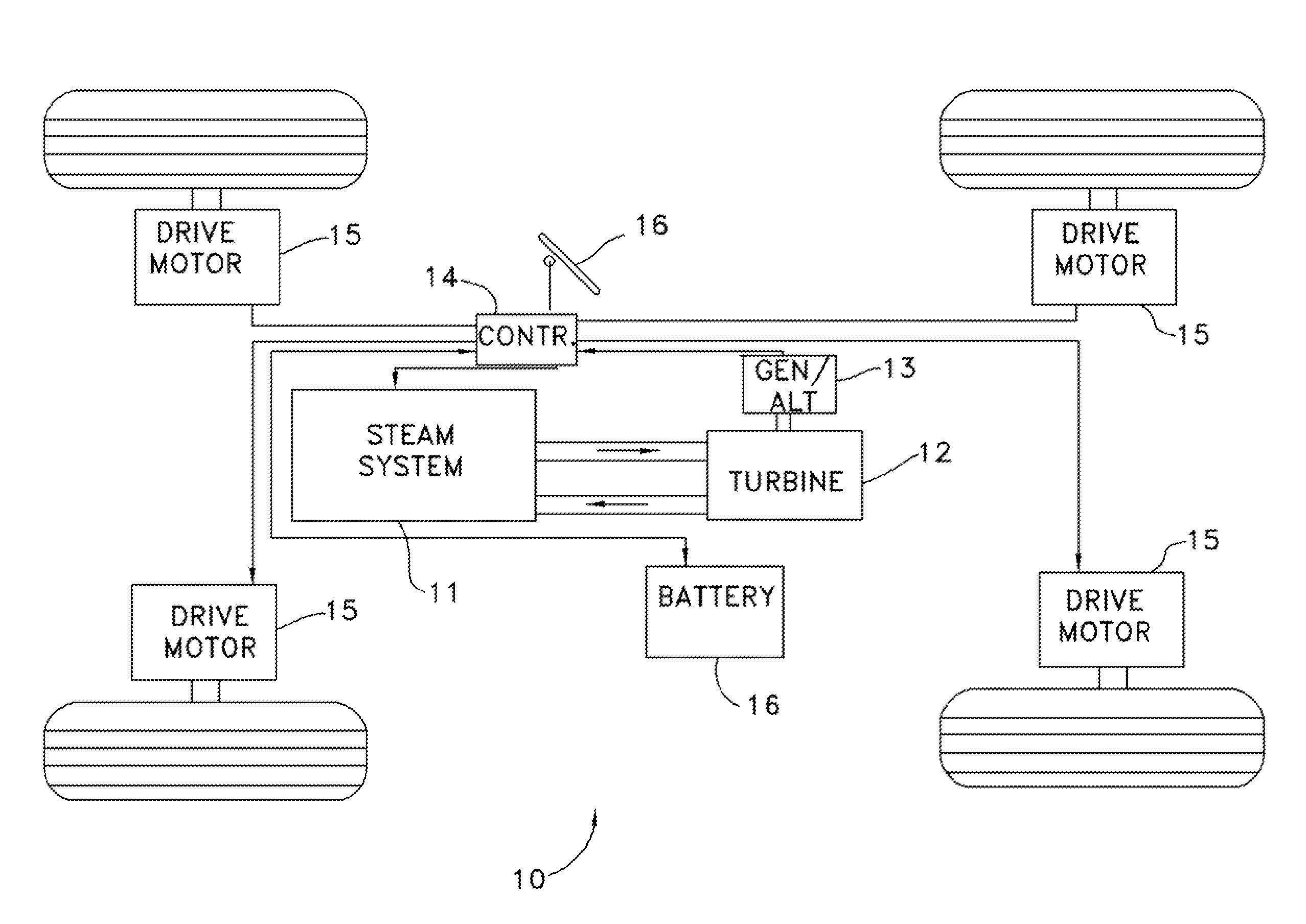
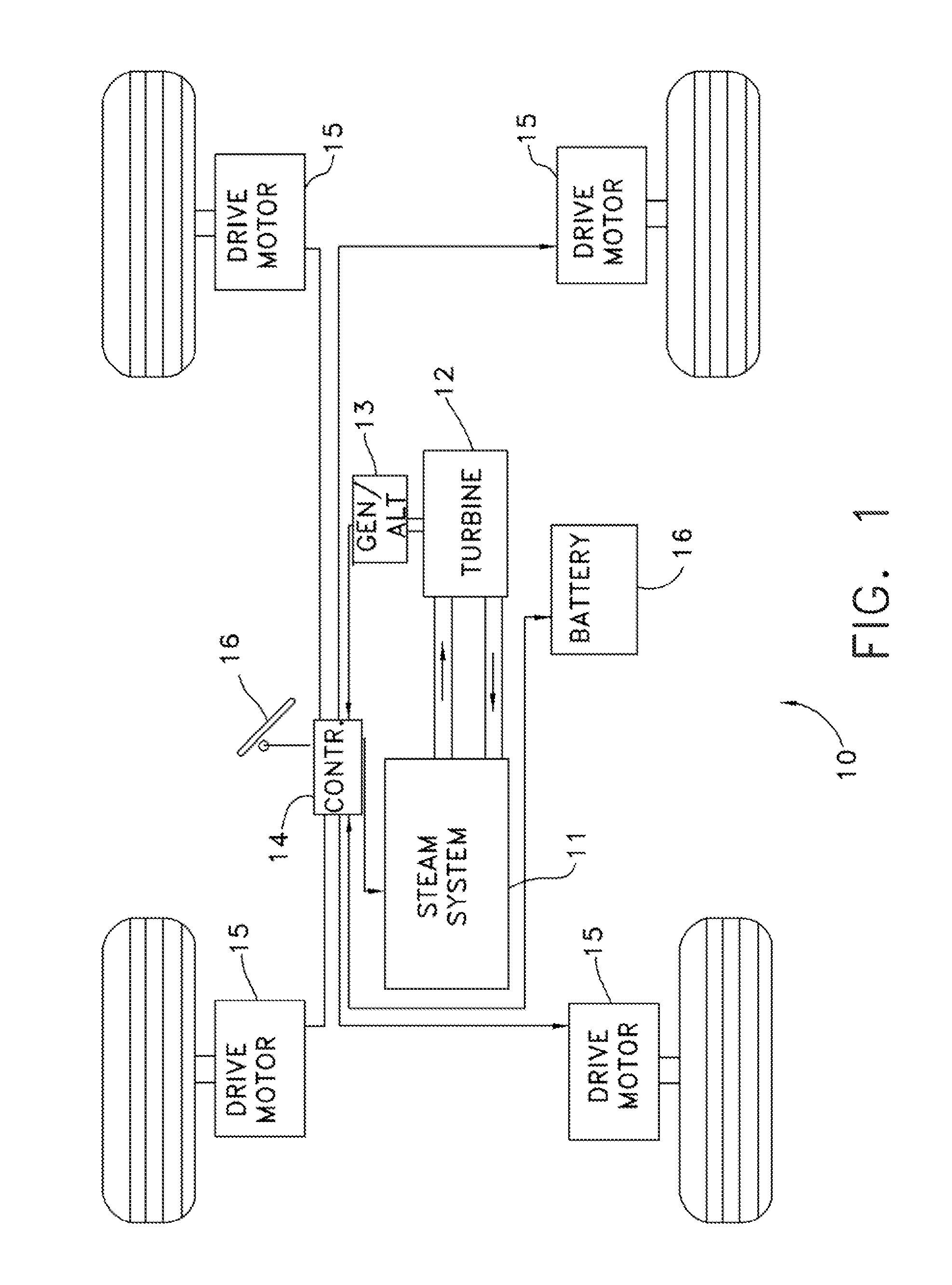
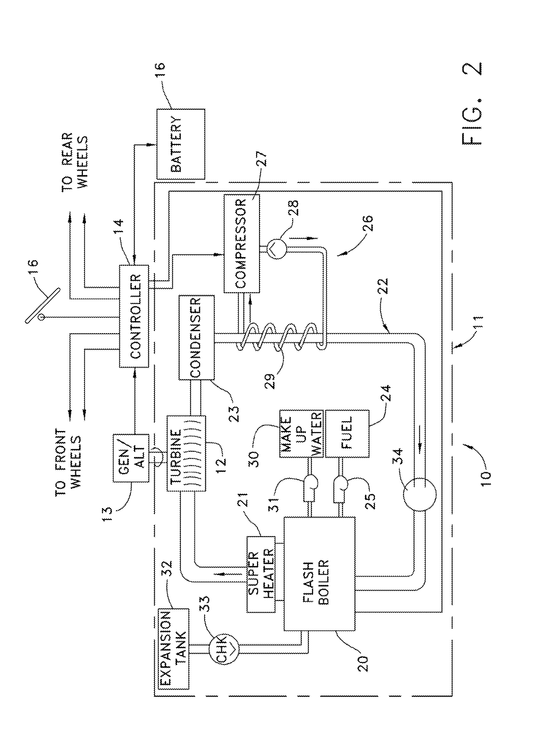
[0018]According to an exemplary embodiment, the power means for the vehicle comprises electric motors at the wheels, and the steam is used to drive a small main drive turbine that operates an alternator for supplying electrical energy to the motor(s). Boiling of the water to produce steam occurs quickly and the system has minimal weight and occupies minimal space, adding to the overall efficiency of the vehicle.

Problems solved by technology

Up until introduction of the electric starter, internal combustion engines relied on a hand crank to start the engine, which was difficult and occasionally dangerous to use, as improper cranking could cause a backfire capable of breaking the arm of the operator.
Electric cars were popular to some extent, but had a short range, and could not be charged on the road if the batteries ran low.
It can use virtually any type of fuel and is exceptionally quiet in operation.
However, early steam cars could take over a minute to start from cold, plus time to get the burner to operating temperature.
This required carrying large quantities of water and / or frequent refilling of the water tank.
Moreover, these early steam systems required large heavy boilers and large capacity vapor systems, thereby decreasing the power-to-weight ratio and reducing the amount of usable space in the vehicle.
The large boilers also increased the amount of time required to heat the water to a usable state.

Method used


Image

  • Vehicle Propulsion System
  • Vehicle Propulsion System
  • Vehicle Propulsion System

Examples


Embodiment Construction

[0025]The word “exemplary” is used herein to mean “serving as an example, instance, or illustration.” Any configuration or design described herein as “exemplary” is not necessarily to be construed as preferred or advantageous over other configurations or designs.

[0026]This invention now will be described more fully hereinafter with reference to the accompanying drawings, in which exemplary embodiments are shown. This invention may, however, be embodied in many different forms and should not be construed as limited to the embodiments set forth herein. Moreover, all statements herein reciting embodiments of the invention, as well as specific examples thereof, are intended to encompass both structural and functional equivalents thereof. Additionally, it is intended that such equivalents include both currently known equivalents as well as equivalents developed in the future (i.e., any elements developed that perform the same function, regardless of structure).

[0027]Thus, for example, it...


PUM


Abstract

A vehicle propulsion system has a sealed, closed loop steam generating system connected to supply steam to drive a small turbine that drives an alternator or generator to produce electrical energy that is supplied to electric traction motors at the wheels of the vehicle to propel the vehicle. According to some of the embodiments, a cooling coil is associated with the steam generating system to facilitate complete and rapid condensing of the steam back to water. At least one battery is connected in the system to supply electrical energy during start up and as otherwise needed. A controller such as a CPU or PC Main Board is connected with the propulsion system to regulate and control distribution of electrical energy to components of the system.

Description

NOTICE OF COPYRIGHT PROTECTION[0001]A portion of the disclosure of this patent document and its figures contain material subject to copyright protection. The copyright owner has no objection to the facsimile reproduction by anyone of the patent document or the patent disclosure, but otherwise reserves all copyrights whatsoever.CO-PENDING, PRIORITY APPLICATION[0002]This application claims priority benefit of Provisional Patent Application, filed Dec. 24, 2009 using U.S. Express Mail No. EH 264 502 076 US and Attorney Docket No. 57595, titled “VEHICLE PROPULSION SYSTEM” having Maurice C. Avery named as the inventor and which Provisional Patent Application is incorporated herein by references as if set forth in full below.FIELD OF THE INVENTION[0003]This invention relates to a power generating and propulsion system for vehicles, and more particularly, to a system that uses a steam-powered turbine to drive a generator or alternator to produce electricity that is supplied to a drive moto...

Claims


Application Information

Patent Timeline
IPC IPC(8): F01K15/02
CPCF22B27/14F01K15/02
Inventor AVERY, MAURICE C.AVERY, CHRIS E.
Owner AVERY MAURICE C
Learn More