Forestry Machines with Transverse Engine and Hydraulic System Installation

Active Publication Date: 2012-06-28
CATERPILLAR INC
View PDF18 Cites 3 Cited by
  • Summary
  • Abstract
  • Description
  • Claims
  • Application Information

AI Technical Summary

Benefits of technology

[0011]In any one or more of the disclosed tractors or methods, the oil supply and fuel tank and hydraulic system may be disposed on one side of the tractor and the engine disposed on an opposite side of the tractor. Other distributions of the engine and hydraulics across the rear of the tractor are possible. In any one or more of the disclosed tractors or methods, the fuel tank may be disposed at least partially above the rear axle. In any one or more of this disclosed tractors or methods, the fuel tank includes an inlet that is accessible to an operator standing on the ground. In any one or more of the disclosed tractors or methods, at least part of the fuel tank

Problems solved by technology

One problem associated with current wheel feller-buncher and site prep tractor designs is the location and orientation of the engine and hydraulic system.
This design provides poor weight distribution across the rear axle and causes many operators to add weight to the rear of the machine to act as a counterbalance.
Further, the excess weight of the counterbalance at the rear of the machine causes fuel and oil reserves to migrate towards the rear the machine,

Method used


Image

  • Forestry Machines with Transverse Engine and Hydraulic System Installation
  • Forestry Machines with Transverse Engine and Hydraulic System Installation
  • Forestry Machines with Transverse Engine and Hydraulic System Installation

Examples


Embodiment Construction

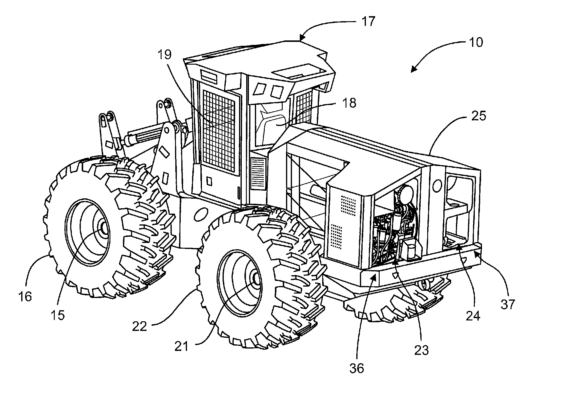
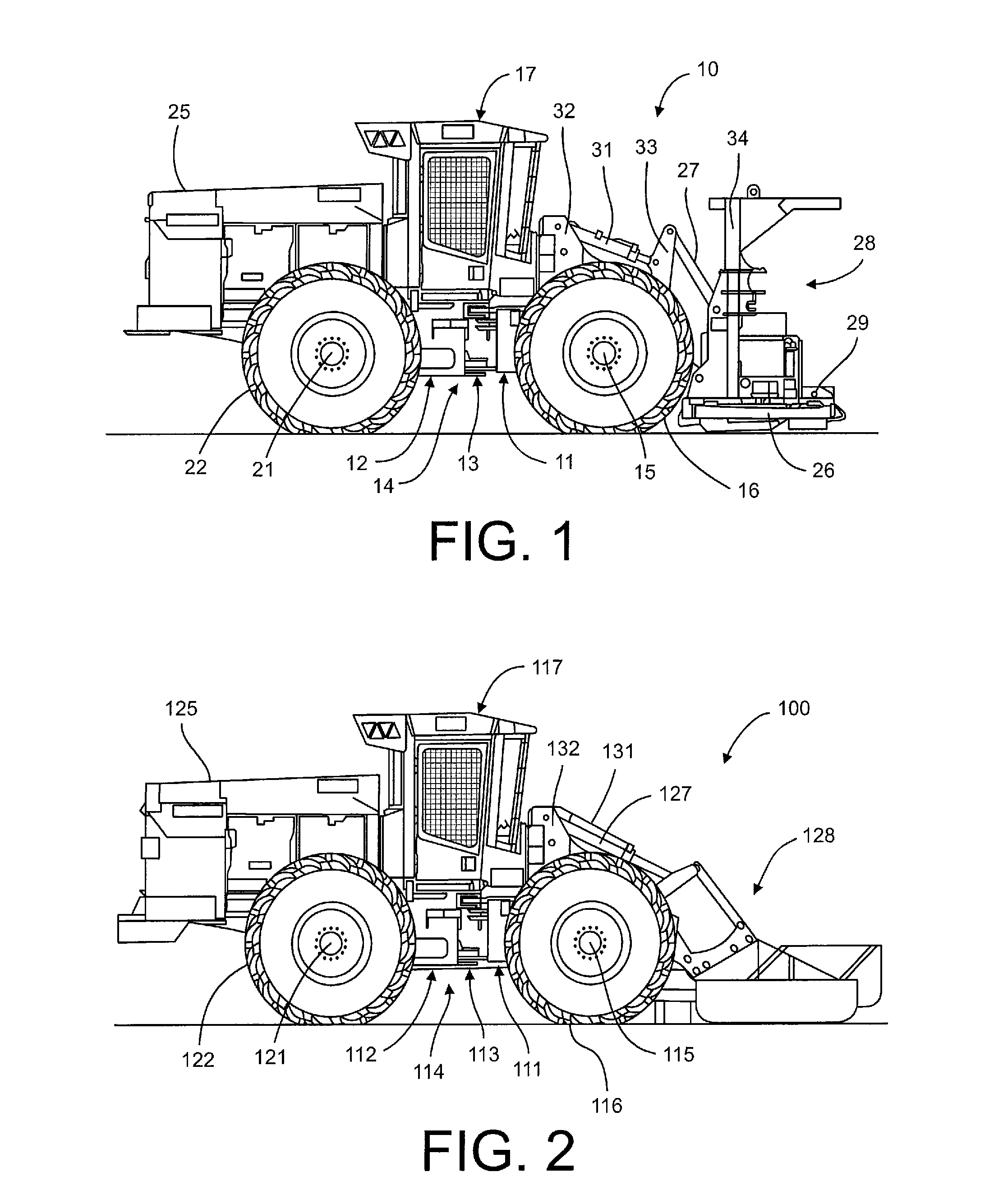
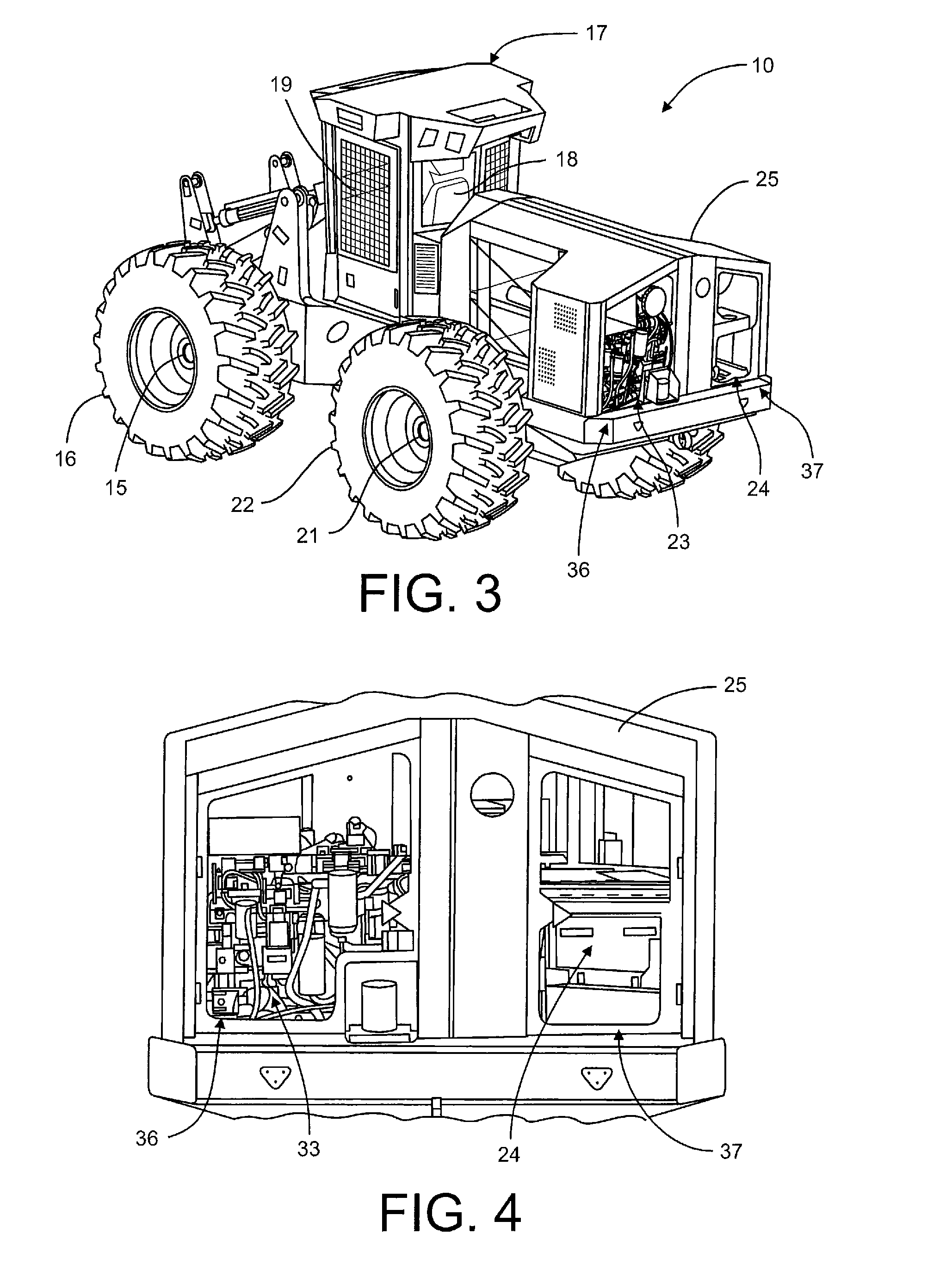
[0021]Referring to FIG. 1, a wheel feller-buncher 10 is shown. The wheel feller-buncher 10 includes a front frame 11 and a rear frame 12. The front frame 11 is pivotally connected to the rear frame 12 via a hitch 13. In particular, the hitch 13 allows the front frame 11 to pivot relative to the rear frame 12 so that the front frame 11, rear frame 12 and hitch 13 provide an articulated chassis 14.

[0022]The front frame 11 is supported by a front axle 15. Two wheels 16 are mounted on the front axle 15. The front frame 11 also supports a cab 17. The cab 17 includes a seat 18 (see FIG. 3) and a number of controls 19 which are manipulated by the operator (not shown) to control various operations of the feller-buncher 10.

[0023]The rear frame 12 is also supported by a rear axle 21. Two wheels 22 are mounted to the rear axle 21. The rear frame 12 also supports an engine 23 and a hydraulic system 24 (see FIG. 3). The engine 23 generates mechanical energy which is transferred to the hydraulic ...


PUM

PropertyMeasurementUnit
Fractionaaaaaaaaaa
Fractionaaaaaaaaaa
Fractionaaaaaaaaaa

Abstract

A wheeled forestry tractors design, such as that for a wheel feller-buncher or a site prep tractor, is disclosed. The disclosed design includes a front axle connected to a rear axle by an articulated chassis. A cab is supported between and above the front and rear axles by the chassis. An engine and a hydraulic system are mounted opposite the rear axle from the cab and in a side-by-side relationship with the engine being aligned transversely with respect to the chassis and parallel to the rear axle. The engine is mounted transversely or parallel with respect to the rear axle and slightly behind the rear axle to improve the weight distribution between the front and rear axles or between the front and rear frames. By mounting the engine transversely and on one side of the rear of the tractor and the hydraulic system on the other side of the tractor in combination with placing the fuel tank in alignment with the engine and the oil tank in alignment with the hydraulic system, improved left to right weight distribution is also achieved.

Description

TECHNICAL FIELD[0001]This disclosure relates generally to forestry machines and, more specifically, to wheeled forestry machines such as wheel feller bunchers and site prep tractors. Still more specifically, this disclosure relates to a transverse engine and hydraulic system installation that provides improved weight distribution and serviceability for wheel feller bunchers and site prep tractors.BACKGROUND[0002]Feller-bunchers are typically used to fell or cut down trees from one site and then bunch the trees together to place them in a pile. Site prep tractors, on the other hand, are typically used to clear brush, tree stumps and other materials from a site. Both feller-bunchers and site prep tractors may be articulated machines that include a front frame and a rear frame that are pivotally coupled together by a hitch. The hitch allows the front frame to pivot relative to the rear frame for steering the feller-buncher or site prep tractor. Both the front and rear frames include an...

Claims


Application Information

Patent Timeline
IPC IPC(8): B60K5/04B23P11/00B60K15/063
CPCB60K5/04B60K15/063B60Y2200/415B60Y2200/417Y10T29/49826B60W2300/50B60K2005/006B60K5/12B60W2300/15
Inventor ROBILLARD, JEROME M.JORGENSEN, CHAD K.
Owner CATERPILLAR INC
Why Eureka
Try Eureka