Actuator

a technology of actuators and rods, applied in the field of actuators, can solve the problems of compromising the design freedom of gun design, and the difficulty of cleaning the dispensing gun, and achieve the effect of preventing the rod from slipping

Inactive Publication Date: 2012-06-28
SULZER MIXPAC AG
View PDF13 Cites 8 Cited by
  • Summary
  • Abstract
  • Description
  • Claims
  • Application Information

AI Technical Summary

Benefits of technology

[0007]The release arrangement enables the release of the locking member by rotation of the rod, thereby dispensing with the need for a locking plate (or corresponding lever) which is separately actuatable by user. Rotation of the rod thus urges the locking member away from a configuration in which it is engaged with (bites on) the rod, preventing the rod's retreat, to disengage the locking member from the rod. The user can release and retreat the rod with a single hand gesture, thereby addressing the problems discussed above and increasing ease of use of the actuator generally.
[0009]In some embodiments, the locking member is forward of the catch member in the one direction. This enables a space efficient arrangement of the actuator in a confined housing, making use of the space forward of the catch member to accommodate the locking member.
[0010]In some embodiments, the actuator provides end of stroke release, releasing the catch member when the rod reaches a predetermined (usually fully advanced) position to prevent further pressure being applied to the rod and the corresponding risk of damaging the actuator and / or dispenser or dispensing cartridge to which the actuator is applied. In these embodiments, the actuator comprises a holding member for holding the catch member in a disengaged relationship with respect to the rod when the rod is advanced to the predetermined position. At this point, further actuation of the trigger member does not advance the rod any further. In some embodiments, the rod comprises a protrusion, for example a pin extending on one or both sides of the rod, for engaging the holding member and thus to advance the holding member with the rod as the rod advances to a predetermined position. In some embodiments, the cam member defines a channel in which this protrusion is slideably accepted to cause the cam member to rotate with the rod. In some embodiments, the holding member is a sleeve disposed between the rod and the cam member, resulting in a compact arrangement in which the rod is supported by the sleeve and cam member to provide a journal close to the actuating mechanism and, in particular, the catch member.
[0015]In some embodiments of the invention, there is provided an actuator for advancing a rod, the actuator comprising means for advancing the rod in response to actuation of a trigger lever and means for preventing retreat of the rod. The actuator further comprises means for releasing the rod in response to rotation of the rod in order to enable retreat of the rod.

Problems solved by technology

The inventors have realized that, for a number of reasons, it may be undesirable to require access to the locking plate or a corresponding release lever or button in order to release the locking plate to allow retreat of the rod.
For example, if the locking plate or lever is arranged such that it can be actuated by the thumb of a user's hand holding the gun to leave the other hand free to retreat the rod, this will compromise the design freedom in designing the gun, in particular for dispensing guns of overall small size.
Similarly, the need for an external locking plate or lever tends to make the dispensing gun more difficult to clean, even if the remaining actuating mechanism is enclosed in a housing.

Method used


Image

  • Actuator
  • Actuator
  • Actuator

Examples


Embodiment Construction

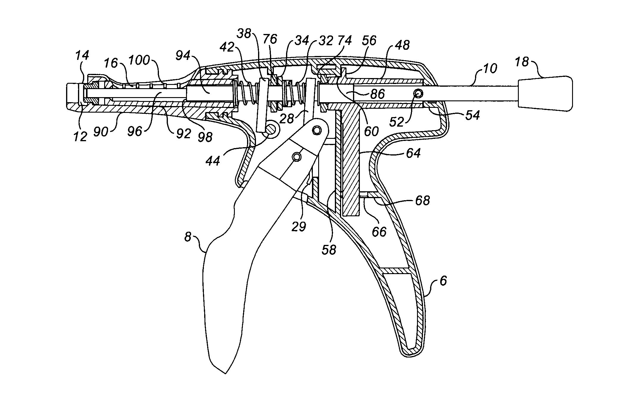
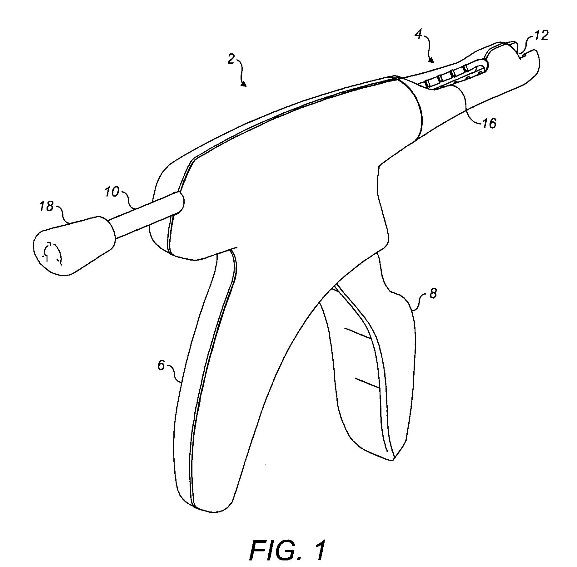
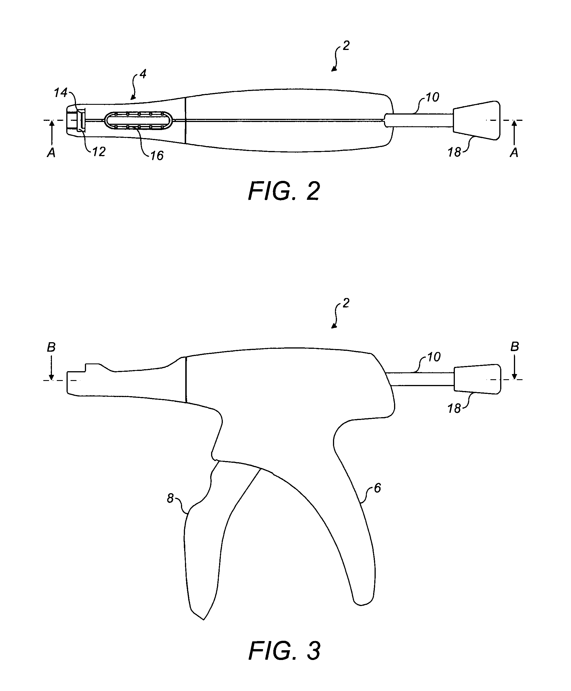
[0025]With reference to FIGS. 1, 2 and 3, a dispenser or applicator comprises an actuator 2 and a cartridge holder 4. The actuator 2 comprises a stock 6 and a trigger lever 8 movable relative to the stock 6. A rod 10 is disposed slideably within the stock 6 and a mechanism inside the stock 6, described in detail below, is arranged such that actuation of the trigger lever 8 causes the rod 10 to advance with respect to the stock 6 and the cartridge holder 4 into a cartridge (not shown) held in a slot 12 of the cartridge holder 4. A positioning member 14 is biased by a disc spring (non shown) to protrude into the slot 12, thereby applying a resilient positioning force to a rear end of the cartridge held in the slot 12. The cartridge holder 4 comprises a window 16 through which the advance of the rod 10 can be observed. At a rear end, the rod 10 carries a knob 18 for enabling a user of the dispenser to rotate the rod 10 in order to release the mechanism inside the stock 6 such that the ...


PUM


Abstract

An actuator for advancing a rod which enables release of the rod from an actuating mechanism by rotating the rod to allow the rod to be retreated. The actuator may also provide a mechanism for disabling the driving mechanism as the rod is fully advanced to prevent damage by excessive forces being applied to the rod. The actuating mechanism can be fully enclosed in a stock of a dispenser gun or applicator, facilitating cleaning of the dispenser gun. The disclosed dispenser gun is particularly suitable for dentistry applications.

Description

RELATED APPLICATION[0001]The present application claims priority to EP Application No. 10196813.9 filed Dec. 23, 2010, which is incorporated herein in its entirety by reference.TECHNICAL FIELD[0002]The present invention relates to an actuator for advancing a rod and, in particular, a dispenser or applicator using such an actuator to apply a dispensing pressure to a viscous material. More particularly, the present invention relates to such a dispenser or applicator for dentistry applications.BACKGROUND ART[0003]Viscous material, such as mastic caulking material, is commonly supplied in a cartridge having a discharge nozzle. The cartridge can be mounted in a dispensing appliance, often called a dispensing gun or applicator. An example of such a dispensing gun is described in British patent GB1555455. The gun has a plunger or a push rod slideably mounted in a cartridge. The cartridge is mounted in a keep before the plunger. The plunger is advanced by means of a catch plate linked to a ...

Claims


Application Information

Patent Timeline
Patent Type & Authority Applications(United States)
IPC IPC(8): B67D7/60F16H21/16F16H25/12
CPCY10T74/1828A61C5/062B05B15/0233B05C17/0126Y10T74/18056A61C5/62B05B15/5225
Inventor BRUMMITT, RICHARD
Owner SULZER MIXPAC AG
Why Eureka
Try Eureka