Wire feeder wire drive design

a feeder wire and wire drive technology, applied in the direction of soldering apparatus, manufacturing tools, welding devices, etc., can solve the problems of electrodes becoming tangled at the rollers, unexpected increases in downstream frictional forces and resistance,

Active Publication Date: 2012-06-28
LINCOLN GLOBAL INC
View PDF44 Cites 28 Cited by
  • Summary
  • Abstract
  • Description
  • Claims
  • Application Information

AI Technical Summary

Benefits of technology

[0005]An exemplary embodiment of the present invention is a wire feeder having at least one roller to be placed in frictional contact with a wire passing through the wire feeder. The roller is free to move in at least one direction normal to an axis of rotation of the roller. The wir

Problems solved by technology

As the electrode is delivered to the torch there can be unexpected increases in downstream frictional forces and resistance in the feeding of the wire to the torch.
These increases in resistance

Method used


Image

  • Wire feeder wire drive design
  • Wire feeder wire drive design
  • Wire feeder wire drive design

Examples


Embodiment Construction

[0012]Exemplary embodiments of the invention will now be described below by reference to the attached Figures. The described exemplary embodiments are intended to assist the understanding of the invention, and are not intended to limit the scope of the invention in any way. Like reference numerals refer to like elements throughout.

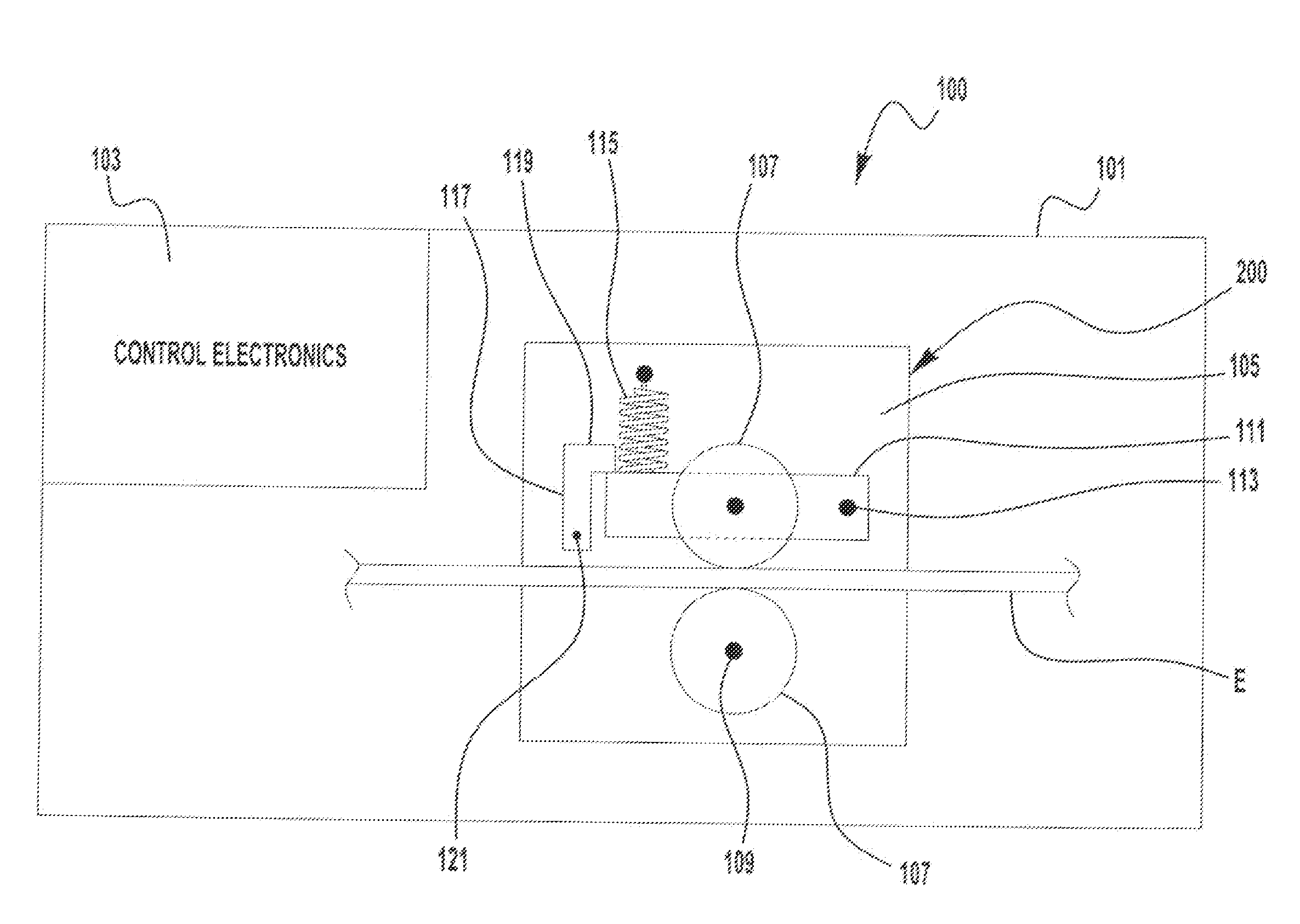
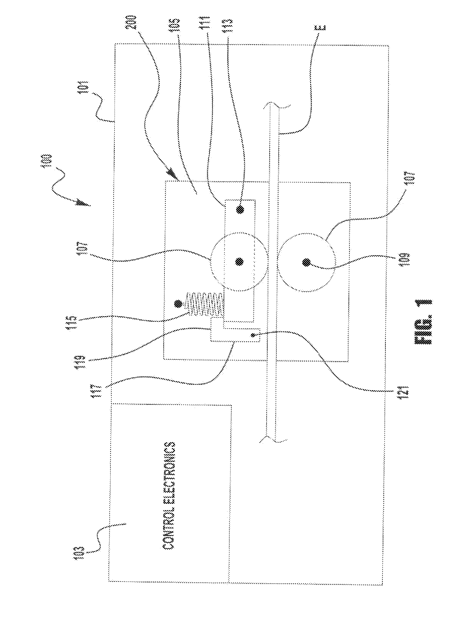
[0013]FIG. 1 is a representative diagrammatical representation of wire feeder 100 incorporating aspects of the present invention. Specifically, the wire feeder 100 has a housing 101, of any suitable construction, control electronics 103 and a wire roller module 200. The control electronics 103 of the wire feeder 100 are electronics used to control the operation and functionality of the wire feeder 100 and a drive motor (not shown) within the wire feeder 100 which drives at least one, if not all, of the rollers 107. Because these electronics are known by those of skill in the art, the electronics will not discussed in detail herein.

[0014]Within the wire fee...


PUM

PropertyMeasurementUnit
Fractionaaaaaaaaaa
Fractionaaaaaaaaaa
Forceaaaaaaaaaa

Abstract

A system and method of feeding wire is provided using at least one roller which is biased towards the wire. The at least one roller is permitted to deflect a limited amount during the wire feeding operation. The roller is permitted to deflect 50% or less than the wire diameter during feeding to prevent tangling.

Description

BACKGROUND OF THE INVENTION[0001]1. Field of the Invention[0002]Devices, systems, and methods consistent with the invention relate to an improved wire drive design for a wire feeder.[0003]2. Description of the Related Art[0004]During welding, such as metal inert gas (MIG) welding, a welding electrode is typically fed to a welding torch by a wire feeder. The wire feeder usually has two or more rollers which are in frictional contact with the electrode and cause the electrode to be advanced to the welding torch. In a two roller configuration, one roller is fixed positionally while the other is biased towards the electrode to provide the frictional contact with the electrode. As the electrode is delivered to the torch there can be unexpected increases in downstream frictional forces and resistance in the feeding of the wire to the torch. These increases in resistance can cause the electrode to buckle at the rollers and this buckling can overcome the biasing force applied to the rollers...

Claims


Application Information

Patent Timeline
IPC IPC(8): B23K37/00B23K3/06
CPCB21F23/00B23K9/125B65H2701/36B23K9/173B65H51/10B23K9/1336
Inventor ENYEDY, EDWARD
Owner LINCOLN GLOBAL INC
Why Eureka
Try Eureka