Ergonomic Head Mounted Display Device And Optical System

a display device and optical system technology, applied in the direction of instruments, polarising elements, planar/plate-like light guides, etc., can solve the problems of preventing the acceptance of technology, heavy weight contributes to fatigue and discomfort, and the technology is not widely accepted. achieve the effect of wide see-through field of view and superior optical performan

Active Publication Date: 2012-06-28
MAGIC LEAP
View PDF10 Cites 534 Cited by
  • Summary
  • Abstract
  • Description
  • Claims
  • Application Information

AI Technical Summary

Benefits of technology

This patent describes an eyewear-like device called an Optical See-Through Head Mounted Display (OSF-HMG). It uses specialized technology to create a seamless blend of virtual and real world images on its screens. The device features a unique glasses-style frame and comfortable earpieces made up of curved surfaces. A thin layer of air between two sheets of transparent material acts like a mirror to allow users to watch their surroundings while wearing the device. Overall, this innovative product offers a high-quality visual experience without sacrificing weight or size.

Problems solved by technology

The technical problem addressed in this patent is the need for an optical see-through head-mounted display (OST-HMD) device that is ergonomically designed, compact, and lightweight with a wide see-through field of view (FOV) and superior performance. Existing HMD designs are heavy, uncomfortable, and limited in their ability to provide a wide FOV. The invention aims to develop a solution with eyeglass form factors and wide FOV while maintaining superior performance.

Method used


Image

  • Ergonomic Head Mounted Display Device And Optical System
  • Ergonomic Head Mounted Display Device And Optical System
  • Ergonomic Head Mounted Display Device And Optical System

Examples


embodiment 6

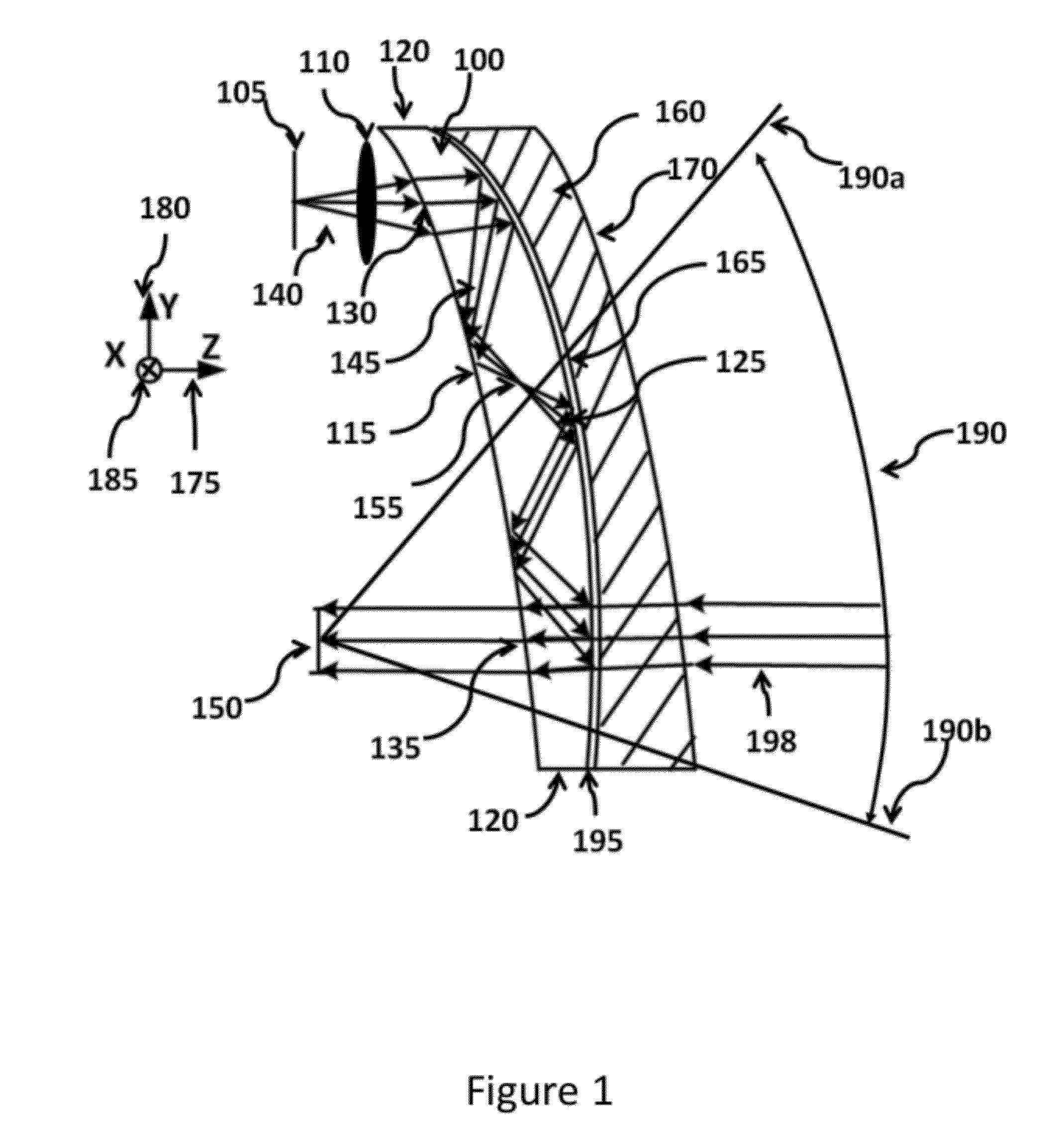
[0105]FIG. 15 shows a ray-tracing example of the see-through path for the The overall corrected see-through FOV is 75° in the horizontal direction and 70° in the vertical direction.

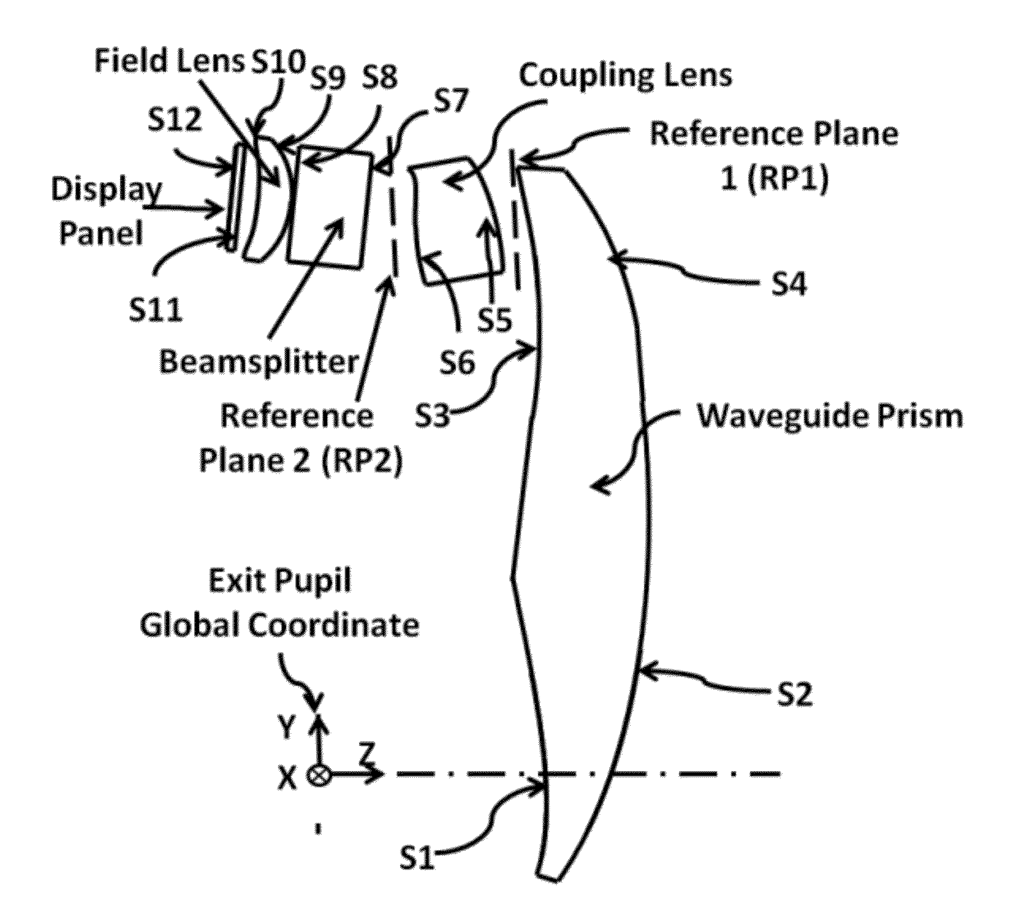
[0106]FIG. 16 shows an illustrative OST-HMD design with a 4-base curve appearance according to the embodiment 6 of the present invention. The OST-HMD device contains a pair of optical assembly of the embodiment 6, a frame 1602, and an electronics unit 1604. Each optical assembly contains the freeform waveguide prism 1600, compensation lens 1660, coupling lens 1610, beam splitter 1605c, field lens 1605b, and a micro-display panel 1605a. The electronics unit 1604 inside the two arms of the frame 1602 can be used to integrate the necessary electronics, which include but not limited to, circuit boards for the micro-display unit and display illumination unit, image and video receiving and processing unit, audio input and output unit, graphic processing unit, positioning unit, wireless communication unit, and ...

embodiment 7

[0112]FIG. 22 shows an untrimmed 3D model of the The model contains the waveguide prism, compensation lens, coupling lens, and field lens. The model also includes a beam splitter space to provide room for inserting a beam splitter to introduce an illumination path for a reflective-type micro-display. The model further includes a cover glass for the micro-display.

[0113]FIG. 23 shows an illustrative OST-HMD design with an 8-base curve appearance according to the embodiment 7 of the present invention. The OST-HMD device contains a pair of optical assembly of the embodiment 7, a frame 2302, and an electronics unit 2304. Each optical assembly contains the freeform waveguide prism 2300, compensation lens 2360, coupling lens 2310, field lens 2305b, and a micro-display panel 2305a. The electronics unit 2304 inside the two arms of the frame 2302 can be used to integrate the necessary electronics, which include but not limited to, circuit boards for the micro-display unit and display illumin...


PUM


Abstract

This invention concerns an ergonomic optical see-through head mounted display device with an eyeglass appearance. The see-through head-mounted display device consists of a transparent, freeform waveguide prism for viewing a displayed virtual image, a see-through compensation lens for enabling proper viewing of a real-world scene when combined together with the prism, and a miniature image display unit for supplying display content. The freeform waveguide prism, containing multiple freeform refractive and reflective surfaces, guides light originated from the miniature display unit toward a user's pupil and enables a user to view a magnified image of the displayed content. A see-through compensation lens, containing multiple freeform refractive surfaces, enables proper viewing of the surrounding environment, through the combined waveguide and lens. The waveguide prism and the see-through compensation lens are properly designed to ergonomically fit human heads enabling a wraparound design of a lightweight, compact, and see-through display system.

Description


Claims


Application Information

Patent Timeline
Owner MAGIC LEAP
Why Eureka
Try Eureka