Unlock instant, AI-driven research and patent intelligence for your innovation.

Electronic device and method for attaching actuation button

a technology of electronic devices and buttons, applied in the field of electronic devices, can solve the problems of increased components, increased labor, and potential risk of button detachment, and achieve the effect of convenient attachmen

Inactive Publication Date: 2012-06-28
ALMEDIO
View PDF3 Cites 1 Cited by
  • Summary
  • Abstract
  • Description
  • Claims
  • Application Information

AI Technical Summary

Benefits of technology

[0006]Accordingly, the present invention aims at providing an electric device that enables easy attachment of an actuation button to a design panel while preventing detachment of the actuation button as well as providing a button attachment method.
[0007]The present invention provides an electronic device comprising: a design panel made of a resin; and an actuation button that is to be attached to the design panel and that has a button portion to accept user's operation while remaining, at least in part, exposed outside and arms connected to the button portion, wherein the design panel includes an insert hole into which the button portion is to be inserted and engagement members that are engaged with portions of the respective arms on the back surface of the design panel in a state of the arms being allowed to move in a plane direction of the design panel, thereby preventing drop of the arms from the design panel.
[0010]Another invention provides a button attachment method for attaching to a design panel of an electronic device an actuation button having a button portion for accepting user's operation and arms connected to the button portion, the method comprising: inserting the button portion into an insert hole formed in the design panel made of a resin; causing portions of the respective arms to engage with engagement members provided on a back surface of the design panel while the arms are allowed to move in a plane direction of the design panel, thereby preventing drop of the arms from the design panel.
[0011]According to the present invention, only the portions of the respective arms are engaged with the corresponding engagement members. Therefore, the actuation button is easily attached to the design panel while detachment of the actuation button is prevented.

Problems solved by technology

The technique described in connection with JP 6-180914 A is directed toward a configuration for attaching an actuation button by means of screw engagement and hence can be said to be laborious.
However, under the technique described in connection with JP 8-116186 A, mere the boss is inserted to the hole, and hence there is a potential risk of detachment of the button.
However, the technique described in connection with JP 2006-164748 A involves a necessity for a new component called a holder member for preventing detachment of the button, which raises a problem of an increase in the number of components and, by extension, a problem of a cost increase.
Another problem is that a once-attached button cannot be detached from the design panel.

Method used


Image

  • Electronic device and method for attaching actuation button
  • Electronic device and method for attaching actuation button
  • Electronic device and method for attaching actuation button

Examples


second embodiment

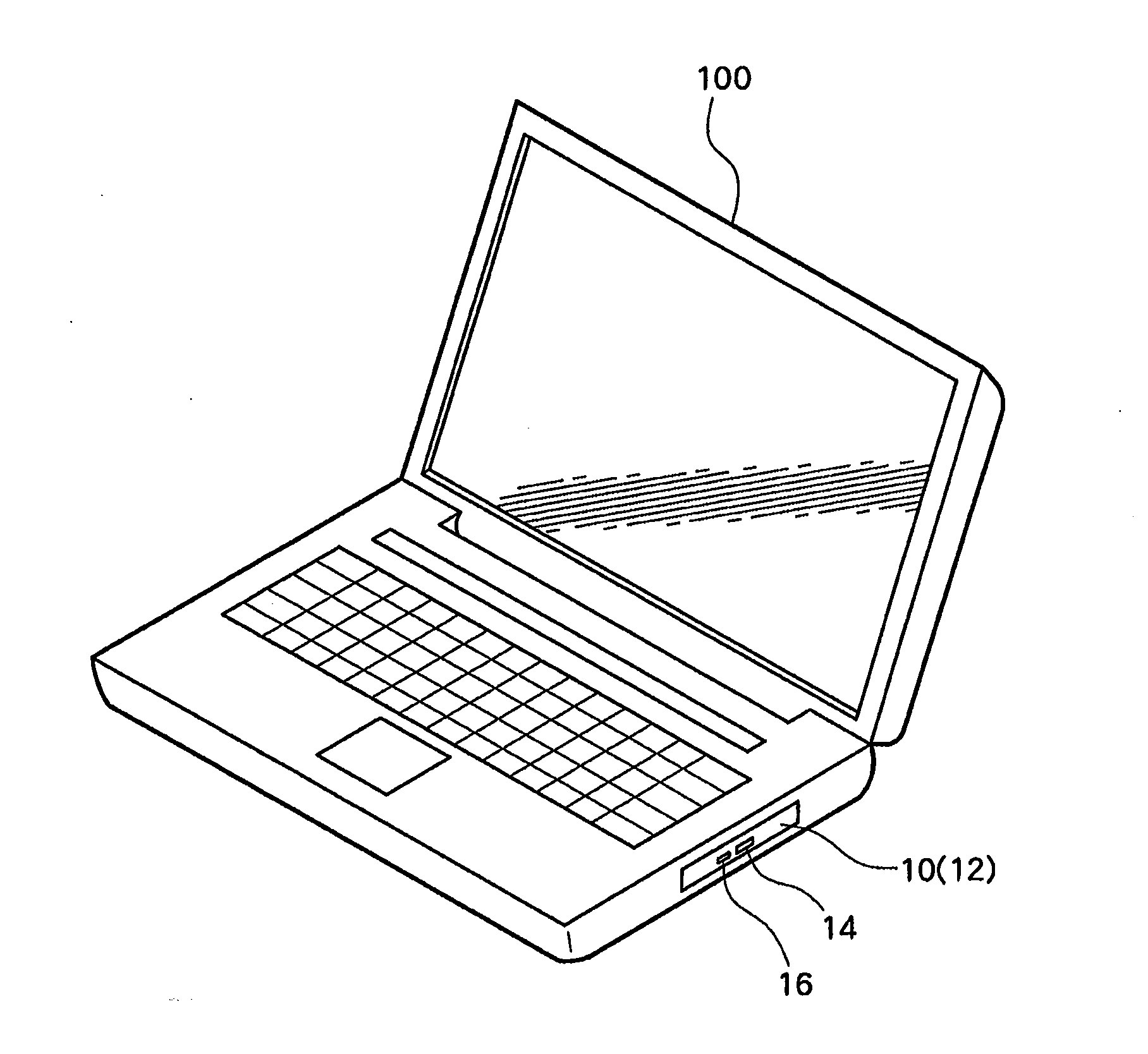
[0058]The design panel 12 employed in the second embodiment is now described by reference to FIGS. 10 and 11. FIG. 10 is a rear view of the design panel 12; FIG. 11 is a cross sectional view taken along line D-D shown in FIG. 10; and FIG. 12 is a cross sectional view taken along line E-E shown in FIG. 10.

first embodiment

[0059]The insert hole 40 into which the main body 24 of the button portion is to be inserted is formed substantially in the center of the design panel 12 as in the The positioning boss 42 to be inserted into the positioning notch 29 is formed at a position above the insert hole 40 on the back surface of the design panel 12.

[0060]The bridge members 48 are formed on right and left sides of the positioning boss 42. The bridge members 48 act as engagement members that are engaged with portions of the respective arms. Each of the bridge members 48 is a region that stands on the back surface of the design panel 12 and that assumes a substantially C-shaped cross sectional profile. A substantially rectangular space 49 is formed between the bridge member 48 and the back surface. The thickness of the space 49 is slightly larger than the thickness of the leading end of the arm 22, and the width of the space 49 is slightly larger than the width of the leading end of the arm 22. The bridge memb...


PUM


Abstract

An electronic device has a design panel 12 made of a resin and an actuation button to be attached to the design panel 12. The actuation button includes a button portion for accepting user's operation and arms 22 connected to the button portion. The design panel 12 has an insert hole 40 into which a main body 24 of the button portion is to be inserted and projecting members 44. The projecting members are engaged with portions of the respective arms 22 on a back surface of the design panel 12 while the arms 22 are allowed to move in a plane direction of the design panel, thereby preventing drop of the arms 22 from the design panel 12.

Description

PRIORITY INFORMATION[0001]This application claims priority to Japanese Patent Application No. 2010-289596, filed on Dec. 27, 2010, which is incorporated herein by reference in its entirety.TECHNICAL FIELD[0002]The present invention relates to an electronic device equipped with a design panel to which an actuation button is to be attached as well as to a method for attaching an actuation button to the design panel.BACKGROUND ART[0003]An electronic device, like an optical disc drive, usually has a design panel that acts as an exterior surface of the electronic device. An actuation button for accepting user's operation is attached to the design panel. The actuation button is attached to the design panel during a manufacturing process, and various techniques have hitherto been put forward in connection with a method for attaching the actuation button.[0004]For instance, JP 6-180914 A describes a technique for attaching arms joined to an eject button to a design panel with screws. Furthe...

Claims


Application Information

Patent Timeline
IPC IPC(8): H05K7/00
CPCG06F1/1656G06F1/1632G06F1/1684
Inventor FUJIMURA, NOBUHIKO
Owner ALMEDIO